Using a Single Phase Power Source
<Figure-2 Typical Single-Phase Configuration>
12.2
Power(HP), Input Current and Output Current
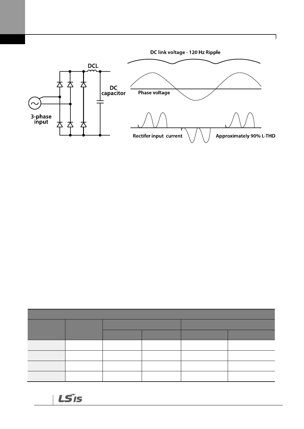
When using a three-phase VFD with single-phase input, derating the drive’s output current and
horsepower will be necessary due to the increase in DC bus ripple voltage and current. In
addition, the input current through the remaining two phases on the diode bridge converter
will approximately double, creating another derating consideration for the VFD. Input current
harmonic distortion will increase, making the overall input power factor low.
Input current distortion over 100% is likely under single-phase conditions without a reactor.
Therefore, the reactor is always required for such applications.
Using a motor that is selected by the three-phase drive ratings with single-phase input may
result in poor performance and premature drive failure.
The selected drive of single-phase current ratings must meet or exceed the motor current
ratings as indicated in the following table.
Single-Phase Current Rating (200V/60Hz)*