• Figures in this manual are shown with covers or circuit breakers removed to show a more
detailed view of the installation arrangements. Install covers and circuit breakers before
operating the inverter. Operate the product according to the instructions in this manual.
• Supply input power within the voltage range approved for the inverter's rating.
• Do not start or stop the inverter using a magnetic contactor installed in the input power supply.
• If the inverter is damaged and loses control, the machine may cause a dangerous situation.
Install an additional safety device, such as an emergency brake, to prevent these situations.
• High levels of current draw during power-on can affect the system. Ensure that correctly rated
circuit breakers are installed to operate safely during power-on situations.
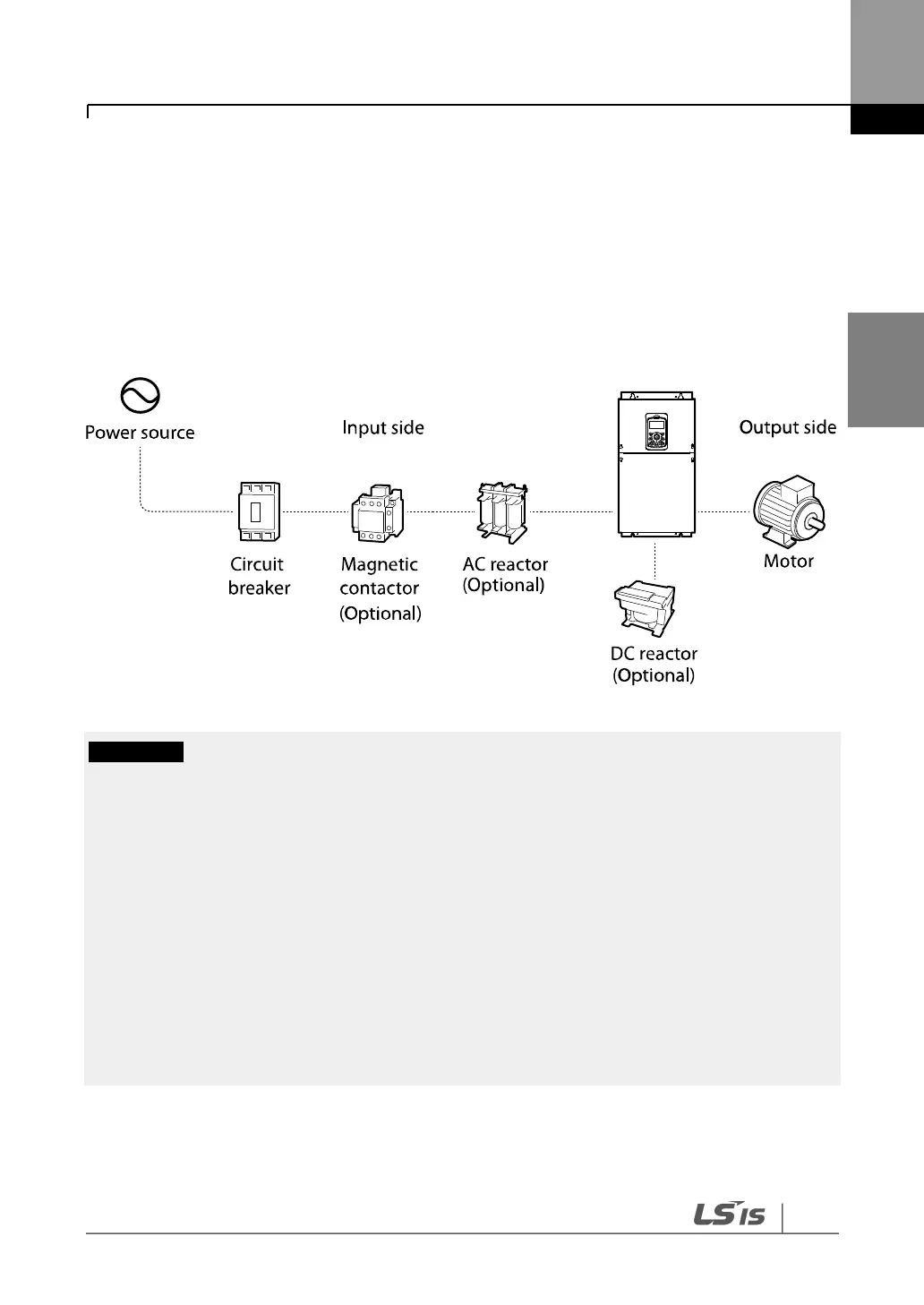
• Reactors can be installed to improve the power factor. Note that reactors may be installed
within 32.8 ft (10 m) of the power source if the input power exceeds 1000 kVA.
• 400 V class inverters require a motor with reinforced insulation. Micro surge voltages generated
at the motor terminals may deteriorate the motor insulation.

 Loading...


