EasyManuals Logo

LSIS SV-IS7 User Manual

LSIS SV-IS7
255 pages
To Next Page IconTo Next Page
To Previous Page IconTo Previous Page
Page #132 background imageLoading...
Page #132 background image
Basic Functions
121
Basic
Functions
6.1.4
Setting a Frequency Reference Using an I/O Expansion
Module (Terminal V2/I2)
After installing an optional I/O I/O expansion moduleto the iS7 inverter, you can set and modify
a frequency reference using the input voltage or current at the V2/I2 terminal.
6.1.4.1
Setting a Reference Frequency using Input Voltage at V2 Terminal
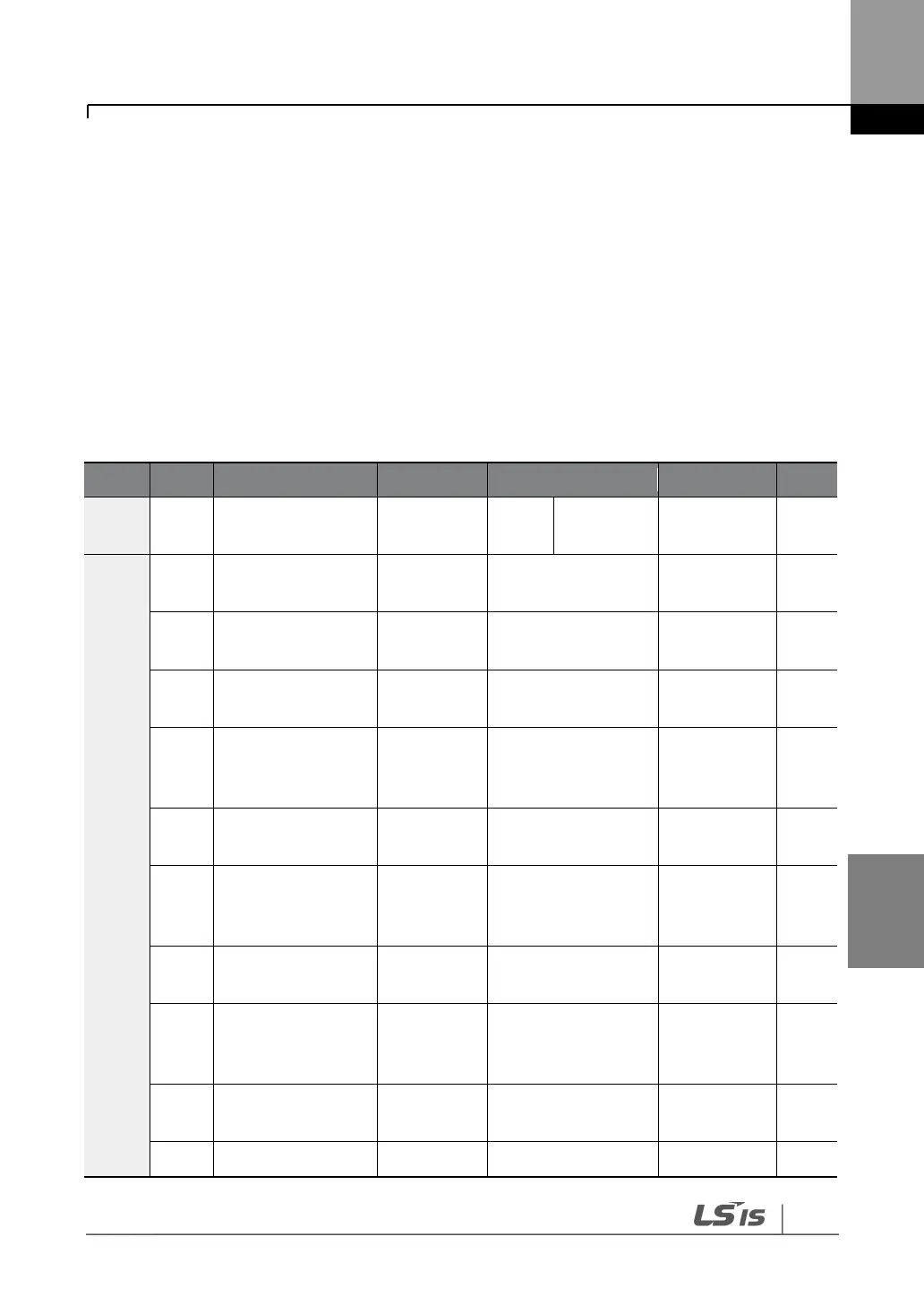
Set the DRV-07 (Frequency reference source) to “4 (V2)and apply an input voltage of -10+12 V
to the V2 terminal.
Group
Code
Name
LCD Display
Parameter Setting
Setting Range
Unit
DRV
07
Frequency
reference source
Freq Ref Src
4
V2
09
-
IN
35
V2 input display
V2 Monitor
0.00
-10.00
+10.00
V
37
V2 input filter time
constant
V2 Filter
10
010000
ms
38
Minimum V2 input
voltage
V2 Volt x1
0.00
0.0010.00
V
39
Output% at
minimum V2
voltage
V2 Perc y1
0.00
0.00100.00
%
40
Maximum V2 input
voltage
V2 Volt x2
10.00
0.0010.00
V
41
Output% at
maximum V2
voltage
V2 Perc y2
100.00
0.00100.00
%
42
Minimum V2 input
voltage
V2 -Volt x1’
0.00
010
V
43
Output% at
minimum V2
voltage
V2 -Perc y1’
0.00
0100
%
44
Maximum V2 input
voltage
V2 -Volt x2’
-10.00
010
V
45
Output% at
V2 -Perc y2’
-100.00
-1000
%

Table of Contents

Questions and Answers:

Question and Answer IconNeed help?

Do you have a question about the LSIS SV-IS7 and is the answer not in the manual?

LSIS SV-IS7 Specifications

General IconGeneral
BrandLSIS
ModelSV-IS7
CategoryInverter
LanguageEnglish

Related product manuals