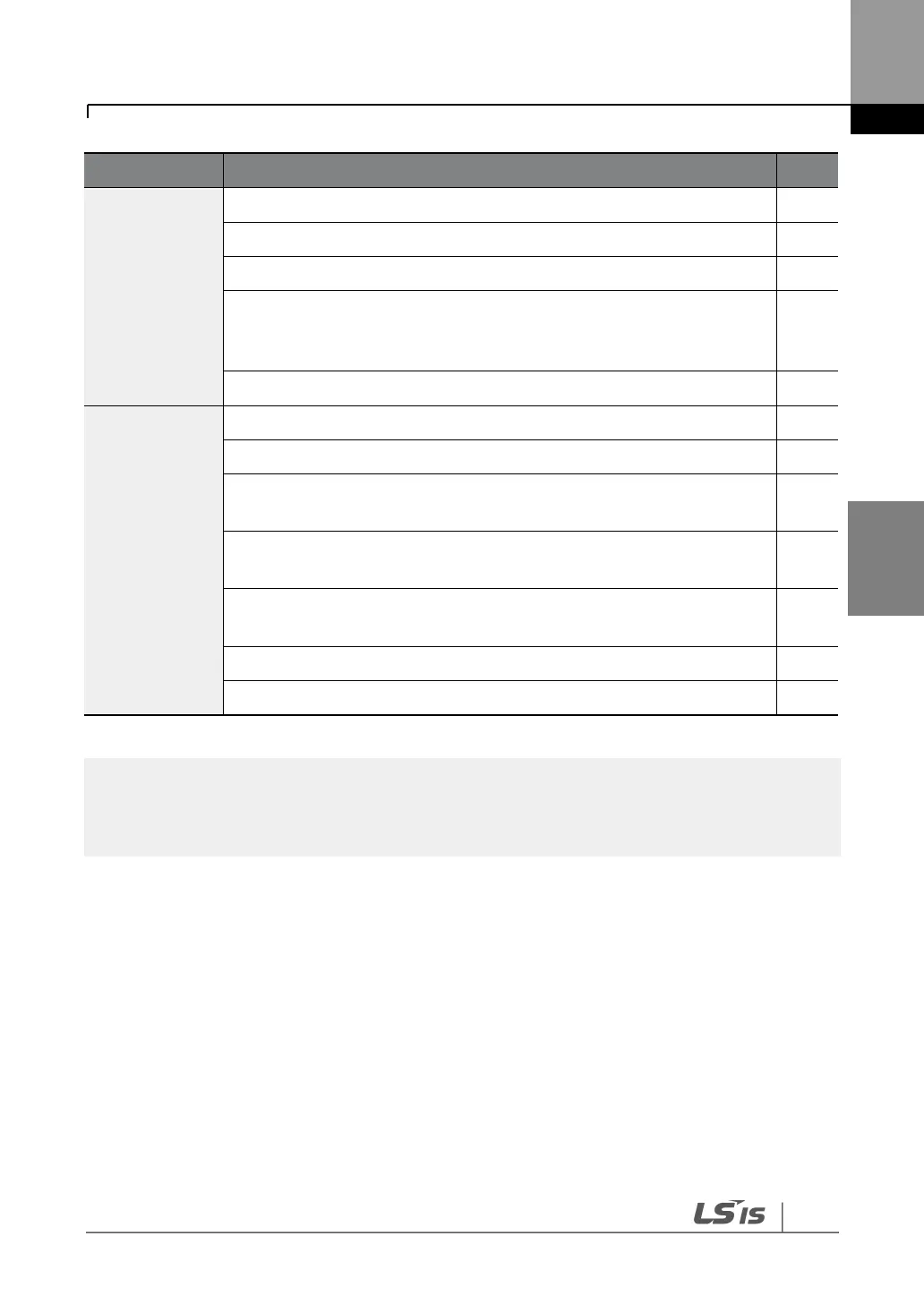
defined prior to the installation of the control wiring connections?
Are the control cables properly wired?
Are the control terminal screws tightened to their specified torques?
Is the total cable length of all control wiring < 328 ft (100 m) for model
types rated at 3.7 kW and below, and 984 ft (300 m) for model types
rated at more than 3.7 kW?
Is the total length of safety wiring < 100 ft (30 m)?
Are optional modules connected correctly?
Is there any debris left inside the inverter?
Are any cables contacting adjacent terminals, creating a potential short
circuit risk?
Are the control terminal connections separated from the power
terminal connections?
Have the capacitors been replaced if they have been in use for > 2
years?
Has a fuse been installed for the power source?
Are the connections to the motor separated from other connections?
STP (Shielded Twisted Pair) cables have a highly conductive, shielded screen around twisted-pair
cables. STP cables protect conductors from electromagnetic interference.
4.15
Test Run
When you turn on the iS7 inverter for the first time, it starts in Easy Start mode to help you
configure the basic parameters required for inverter operation.
4.15.1
Entering Easy Start Mode
The inverter starts in Easy Start mode when you turn on the inverter for the first time, or when
the inverter is turned on following a parameter initialization.