4.6.5
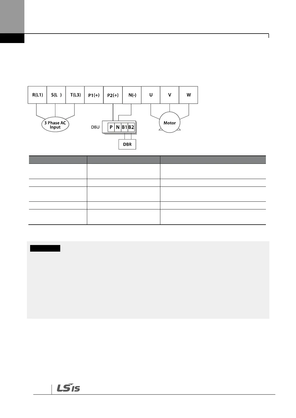
280–375 kW (200 V/400 V)
Connect the cables from the dynamic braking unit to the P2 (+) and N (-) terminals to utilize the
built-in dynamic braking unit.
AC power supply input
terminals
(+) DC link voltage terminal
Dynamic brake resistor
terminal / DC common*
Dynamic brake resistor terminals
(-) DC link voltage terminal
Inverter output terminals
Output terminals to a 3-phase induction
motor
*Contact LSIS Customer Support before configuring the P2 (+) and N (-) terminals as the DC common
source. There are a few factors that require special attention for this application.
• Apply rated torques to the terminal screws. Loose screws may cause the terminals to short
circuit and malfunction. Tightening the screws too much may damage the terminals and cause
them to short circuit and malfunction.
• Only use copper wires with a 600 V, 75 ℃ rating for the power terminal wiring, and a 300 V,
75 ℃ rating for the control terminal wiring.
• Power supply wiring must be connected to the R, S, and T terminals. Connecting them to the U,
V, W terminals causes internal damage to the inverter. The motor should be connected to the U,
V, and W terminals. Arrangement of the phase sequence is not necessary.