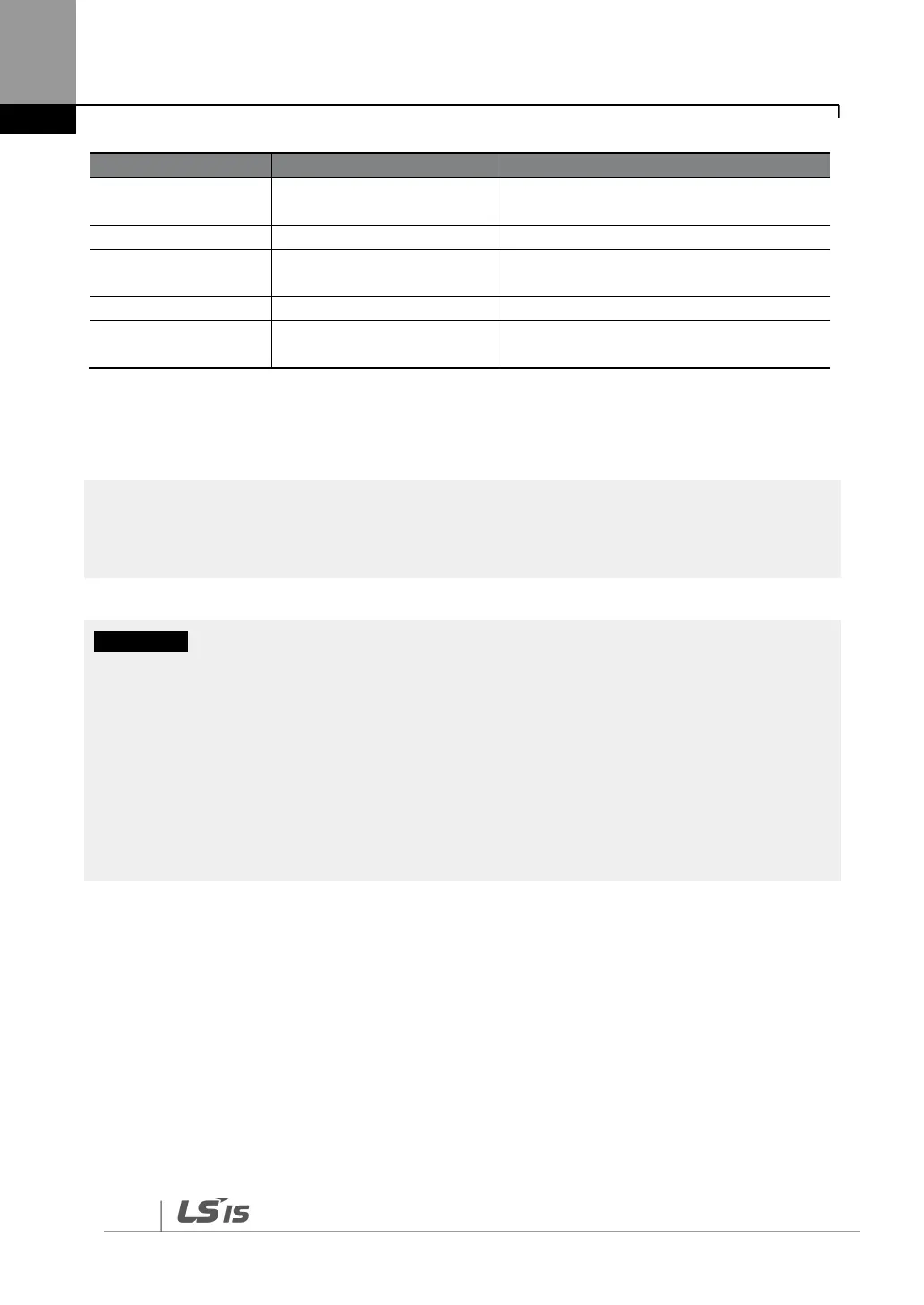
AC power supply input
terminals
(+) DC link voltage terminal
Dynamic brake resistor
terminal / DC common*
Dynamic brake resistor terminals
(-) DC link voltage terminal
Inverter output terminals
Output terminals to a 3-phase induction
motor
*Contact LSIS Customer Support before configuring the P2 (+) and N (-) terminals as the DC common
source. There are a few factors that require special attention for this application.
External DC reactors cannot be used with 30–75 kW inverters. To use a DC reactor with these
inverters, purchase a 30–75 kW inverter that has a built-in DC reactor.
• When a built-in DCR unit is present, the P1 (+) and P (-) terminals are connected to the reactor’s
input and output terminals respectively.
• If your product does not have a built-in DCR unit, the P2 (+) and N (-) terminals may be used as
the common DC source. Do not use the P1 (+) terminal as the common DC source, as this may
result in product damage.
• Use the P2 (+) and N (-) terminals to connect a dynamic braking resistor to the inverter. Do not
connect the dynamic braking unit to the P1 (+) terminal, as this may result in product damage.
• Contact LSIS Customer Support before configuring the N (-) terminal as the DC common source.
There are a few factors that require special attention for this application.
4.6.3
90–160 kW (400 V)
Connect the cables from the dynamic braking unit to the P2 (+) and N (-) terminals to utilize an
external dynamic braking unit.