8
Table of Functions
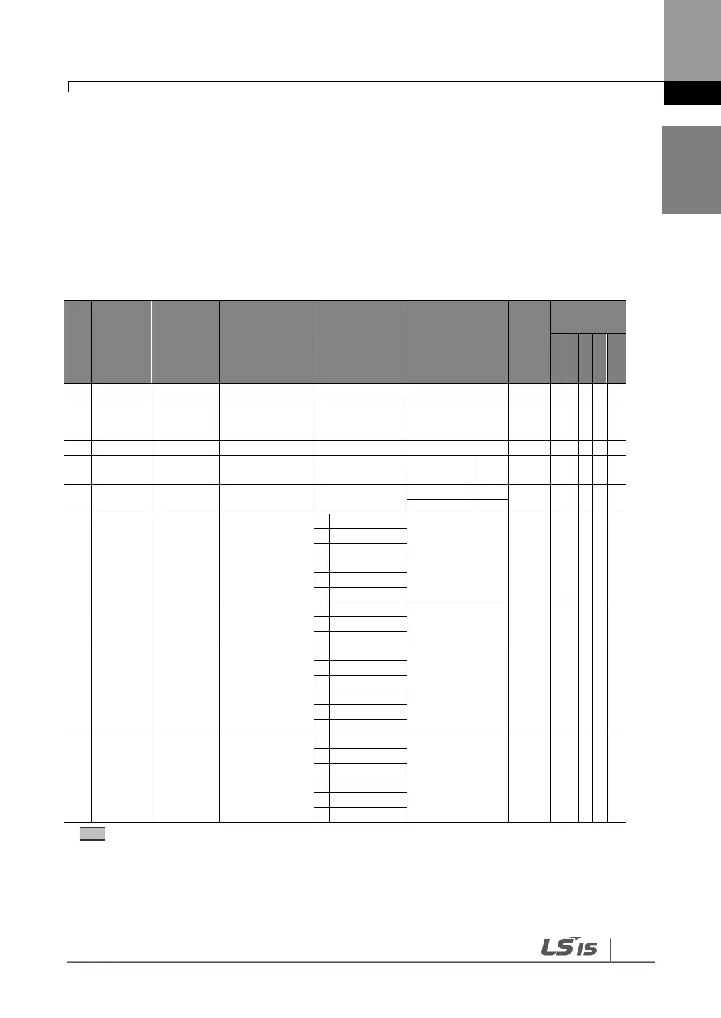
8.1
Parameter Mode – DRV Group (DRV)
DRV Group (PAR DRV)
Starting frequency
-maximum
frequency (Hz)
Frequency
reference source
* The grey cells indicate a hidden code which is only visible when setting a code.
Note 1)
Effectiveness of each code according to the Control Mode setting.
V/F: V/Fmode (PG included), SL: Sensorless-1, 2 mode, VC: Vector mode, SLT: Sensorless-1, 2 Torque
mode,
VCT: Vector Torque mode, Refer to the Options manual for options.