Using a Single Phase Power Source
12.4
Wiring and Peripheral Device
It is important that input wiring and branch circuit protection be selected based on the drive’s
single-phase input current rating indicated in Table 1–2.
The single-phase input current after derating differs from the three-phase input indicated on
the VFD nameplate.
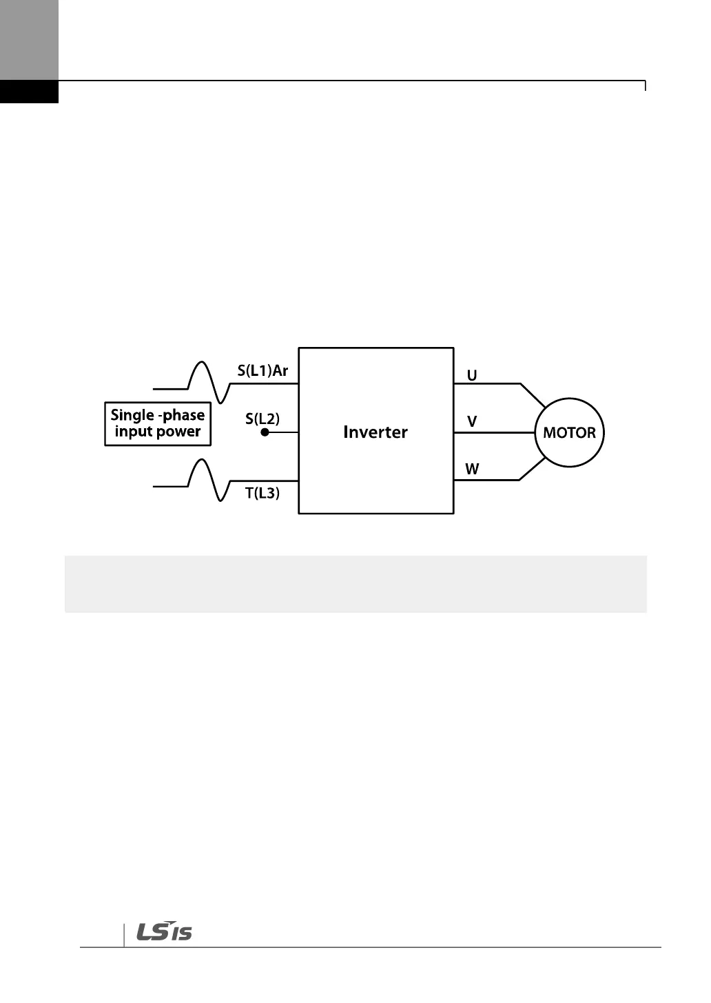
Refer to the following figure and connect the single-phase AC input wiring to the inverter’s R[L1]
and T[L3] terminals.
<Figure-3 Terminal Wiring Diagram>
The drive ratings in Table 1 are valid for 60 Hz input only.

 Loading...


