AC power supply input terminals
(-) DC link voltage terminal
Dynamic brake resistor terminal
Dynamic brake resistor terminals
Inverter output terminals
Output terminals to a 3-phase
induction motor
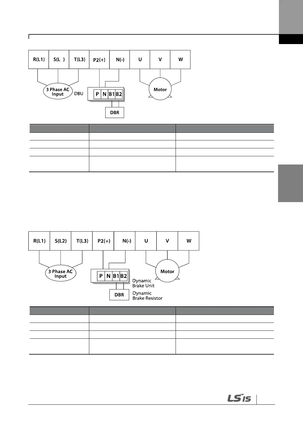
4.6.4
185–220 kW (400 V)
Connect the cables from the dynamic braking unit to the P2 (+) and N (-) terminals to utilize an
external dynamic braking unit.
AC power supply input terminals
(-) DC link voltage terminal
Dynamic brake resistor terminal
Dynamic brake resistor terminals
Inverter output terminals
Output terminals to a 3-phase
induction motor