9.1.5
Indicators on the DB unit
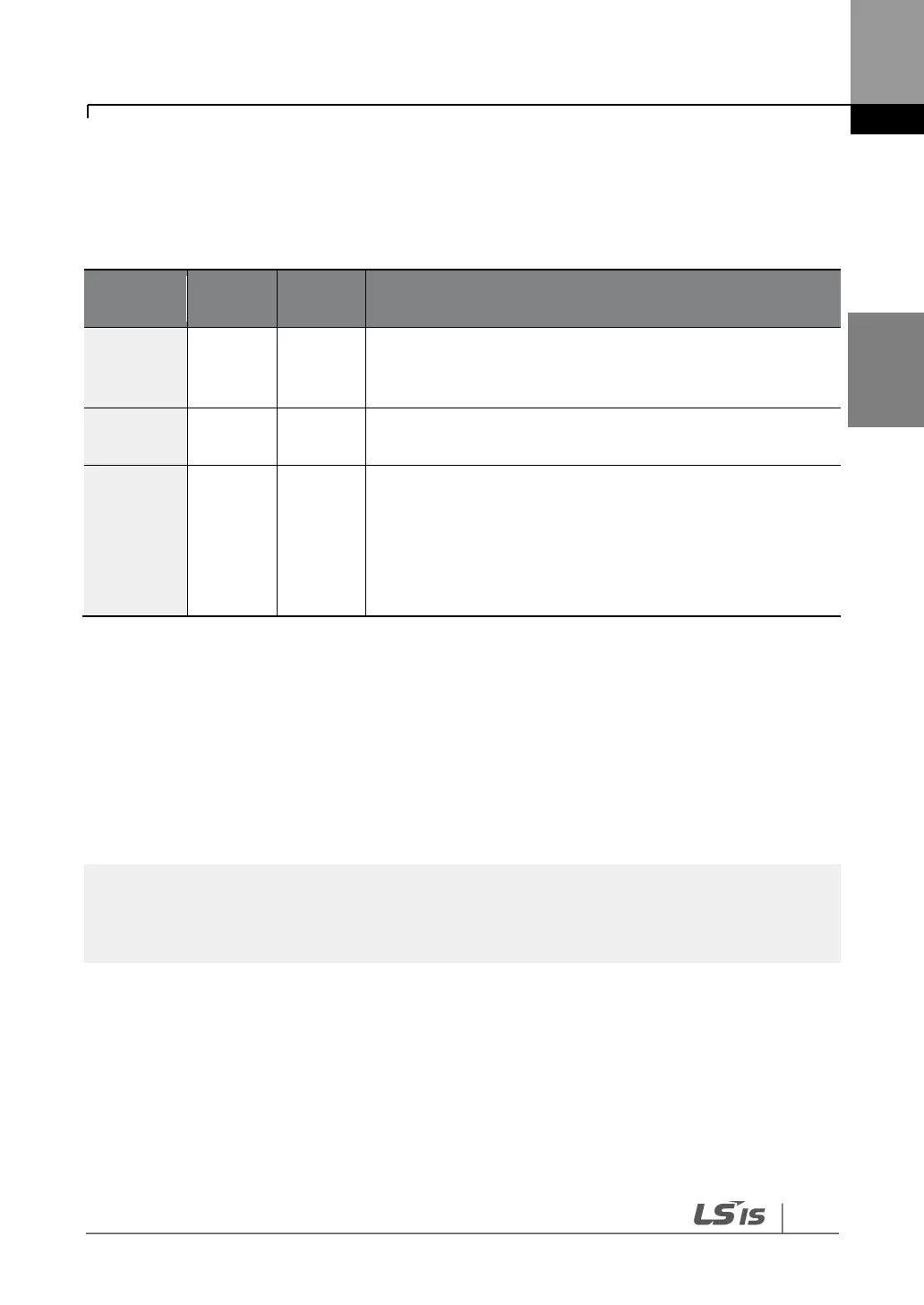
On a DB unit, there are three LED indicators (one red and two green indicators) that indicate
the operating condition of the DB unit.
Turns on when the main power is supplied to the unit (if a DB
unit is connected to an inverter, the power indicator is turned
on when the main power is supplied to the inverter).
Turns on when the DB unit is regenerating.
Turns on when the overheating protection function is
enabled.
If the DB unit temperature exceeds the maximum allowed
operating temperature, the overheating protection function
is activated to cut off the input to the DB unit (the power
indicator on the DB unit is turned off).
9.1.6
DB Resistors
The following table lists type A DB unit specifications for your reference. For type B and type C
DB unit specifications, refer to the instruction manuals that are supplied with the DB units.
Before installing a DB resistor, refer to the instruction manuals provided by the manufacturer
to choose an appropriate type of DB resistor.
When you double the duty cycle (%ED) of a DB unit, the wattage ratings of the optional DB resistor
must be doubled accordingly.