• The TR (termination resistor) switch is used to terminate the RS485 network connection (120 Ω).
• Use a potentiometer rated for 0.5 W, 1 kΩ.
If the analog voltage (V) or current (I) input is used to set the frequency reference, the analog
input is reflected when the input is actually received. For instance, the voltage input 0 V at V1
does not indicate that no input is received at V1, but it means that 0 V input is actually received
at V1.
When you use the analog voltage input, the bipolar input range (-10 – +10V), in comparison to the
unipolar input range (0–10V), allows for more accurate input control with smaller increments.
If the analog input is interrupted when setting a frequency reference using the analog voltage (V)
input and no voltage input is received at the terminal, an offset voltage may be applied to keep the
frequency reference at approximately 4–5 Hz.
4.10
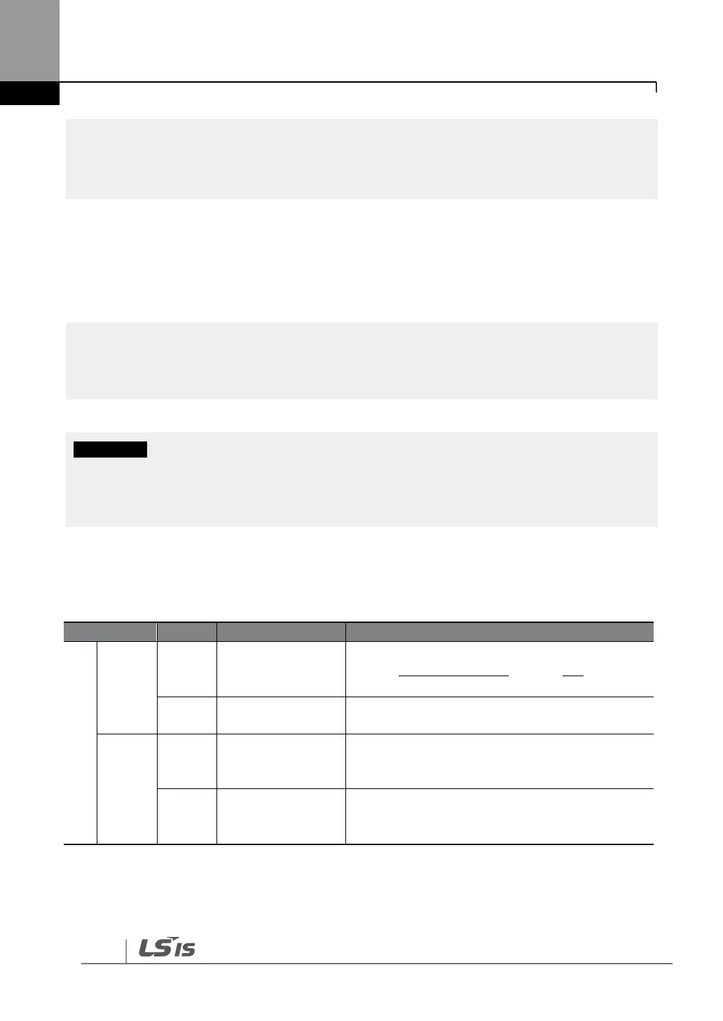
Terminal Inputs for Inverter Operation
Configurable for multi-function input terminals.
Refer to 8 Table of Functions on page 154 for the
multi-function terminal configurations.
Common terminal for terminal inputs (5G common
terminal is used for analog frequency inputs only).
Potentiometer
frequency reference
(+)
Used to setup or modify a frequency reference via
the analog voltage or current input.
Maximum output is +12 V, 100 mA.
Potentiometer
frequency reference
(-)
Used to setup or modify a frequency reference via
the analog voltage or current input.
Maximum output is -12 V, 100 mA.