Troubleshooting and Maintenance
Troubleshooting
/Maintenance
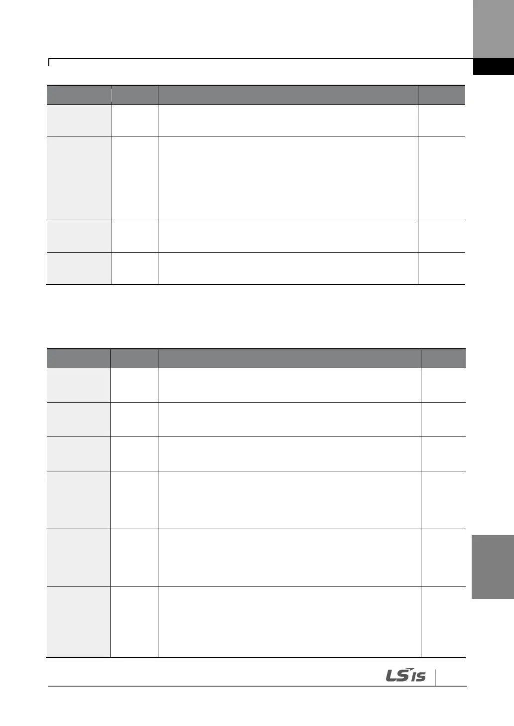
phases in an open circuit condition. Operates only when bit
2 of PRT-05 is set to “1”.
Displayed when the inverter has been protected from
overload and resultant overheating, based on inverse time
limit thermal characteristics. Allowable overload rates for
the inverter are 150% for 1 min and 200% for 4 sec.
Protection is based on the inverter rated capacity, and may
vary depending on the device’s capacity.
Displayed when the internal DC circuit voltage is less than
the specified value during inverter operation.
Displayed when a safety feature is activated to block the
inverter output during an emergency.
7.1.2
Abnormal Circuit Conditions and External Signals
Displayed when the inverter DC fuse is exposed to an
overcurrent above 30 kW.
Displayed when the temperature of the inverter heat sink
exceeds the specified value.
Displayed when the DC circuit in the inverter detects a
specified level of excessive, short circuit current.
Displayed when an external fault signal is provided by the
multi-function terminal. Set one of the multi-function input
terminals at IN-65–72 to “3 (External Trip)” to enable external
trip.
Displayed when the inverter output is blocked by a signal
provided from the multi-function terminal. Set one of the
multi-function input terminals at IN-65–71 to “4 (BX)” to
enable the input block function.
Displayed when an error is detected in the memory
(EEPRom), analog-digital converter output (ADC Off Set), or
CPU watchdog (Watch Dog-1, Watch Dog-2).
EEP Err: An error in reading/writing parameters due to a
keypad or memory (EEPRom) fault.