EasyManuals Logo

LSIS SV-IS7 User Manual

LSIS SV-IS7
255 pages
To Next Page IconTo Next Page
To Previous Page IconTo Previous Page
Page #72 background imageLoading...
Page #72 background image
Connecting the Cables
Connecting
the Cables
61
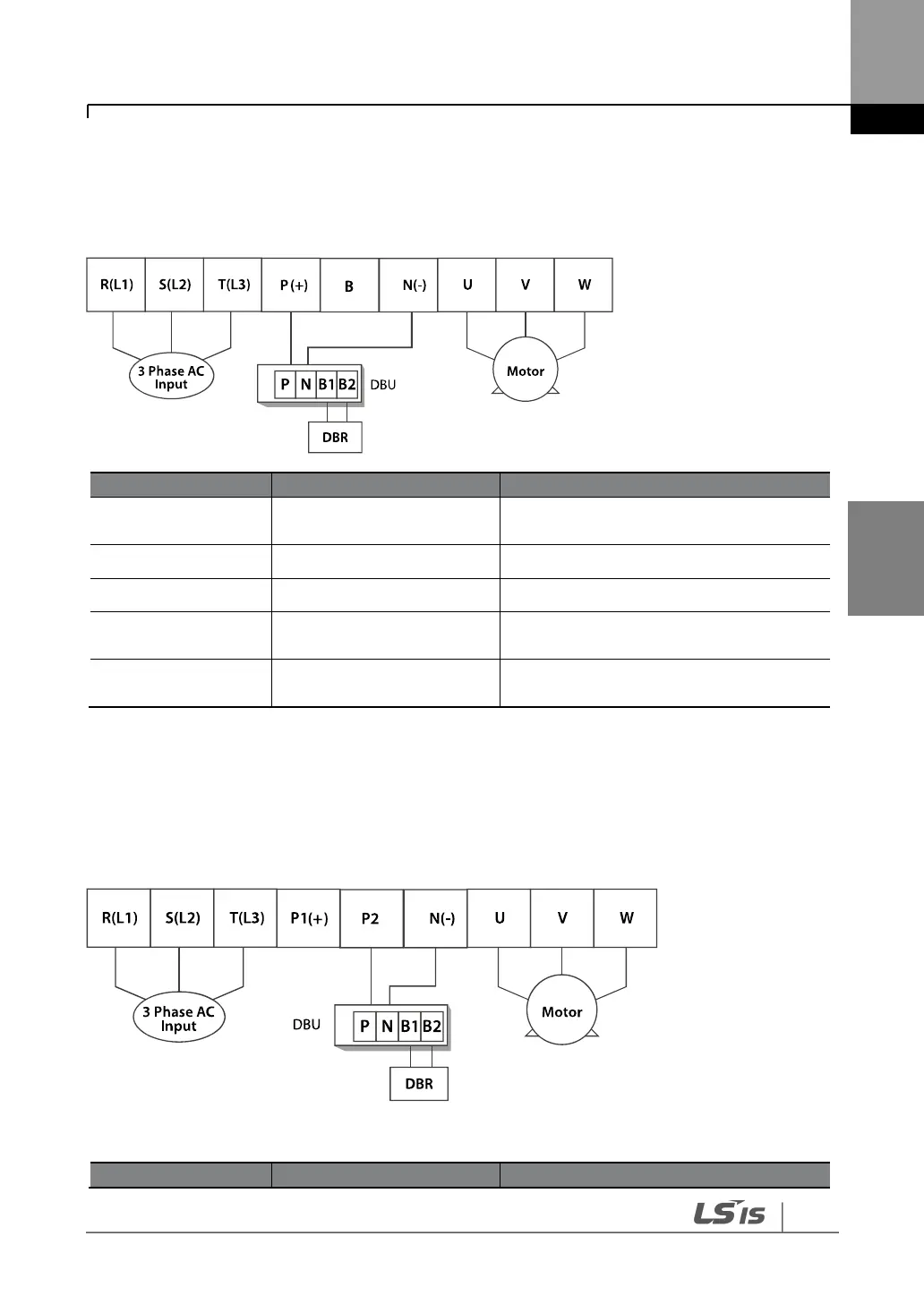
Cable connection for utilizing the optional dynamic braking unit
Connect the cables from dynamic braking unit to P (+) and N (-) terminals to utilize the optional
dynamic braking unit. Do not connect cables to B terminal.
Terminal Symbol
Terminal Name
Description
R (L1), S (L2), T (L3)
AC power supply input
terminals
AC input terminals
P (+)
(+) DC voltage terminal
(+) DC link voltage terminal
N (-)
(-) DC voltage terminal
(-) DC link voltage terminal.
P (+), B
Dynamic brake resistor
terminals
Dynamic brake resistor terminals
U, V, W
Inverter output terminals
Output terminals to a 3-phase induction
motor
4.6.2
3075 kW (200 V/400 V)
Connect the cables from the dynamic braking unit to the P (+) and B terminals to utilize the
built-in dynamic braking unit.
In 30-75 kW 200 V model types, the P1 and P2 terminals are connected with a jumper pin.
Terminal Symbol
Terminal Name
Description

Table of Contents

Questions and Answers:

Question and Answer IconNeed help?

Do you have a question about the LSIS SV-IS7 and is the answer not in the manual?

LSIS SV-IS7 Specifications

General IconGeneral
BrandLSIS
ModelSV-IS7
CategoryInverter
LanguageEnglish

Related product manuals