Troubleshooting and Maintenance
disappears.
Fatal: When the fault is corrected, the fault trip or warning signal disappears only after the user
turns off the inverter, waits until the charge indicator light goes off, and turns the inverter on again.
If the inverter is still in a fault condition after it is powered on again, please contact the supplier or
the LSIS Customer Support.
The function for saving the fault history and the fault signal output may not be performed if the
functions are not set or the inverter is seriously damaged.
7.2
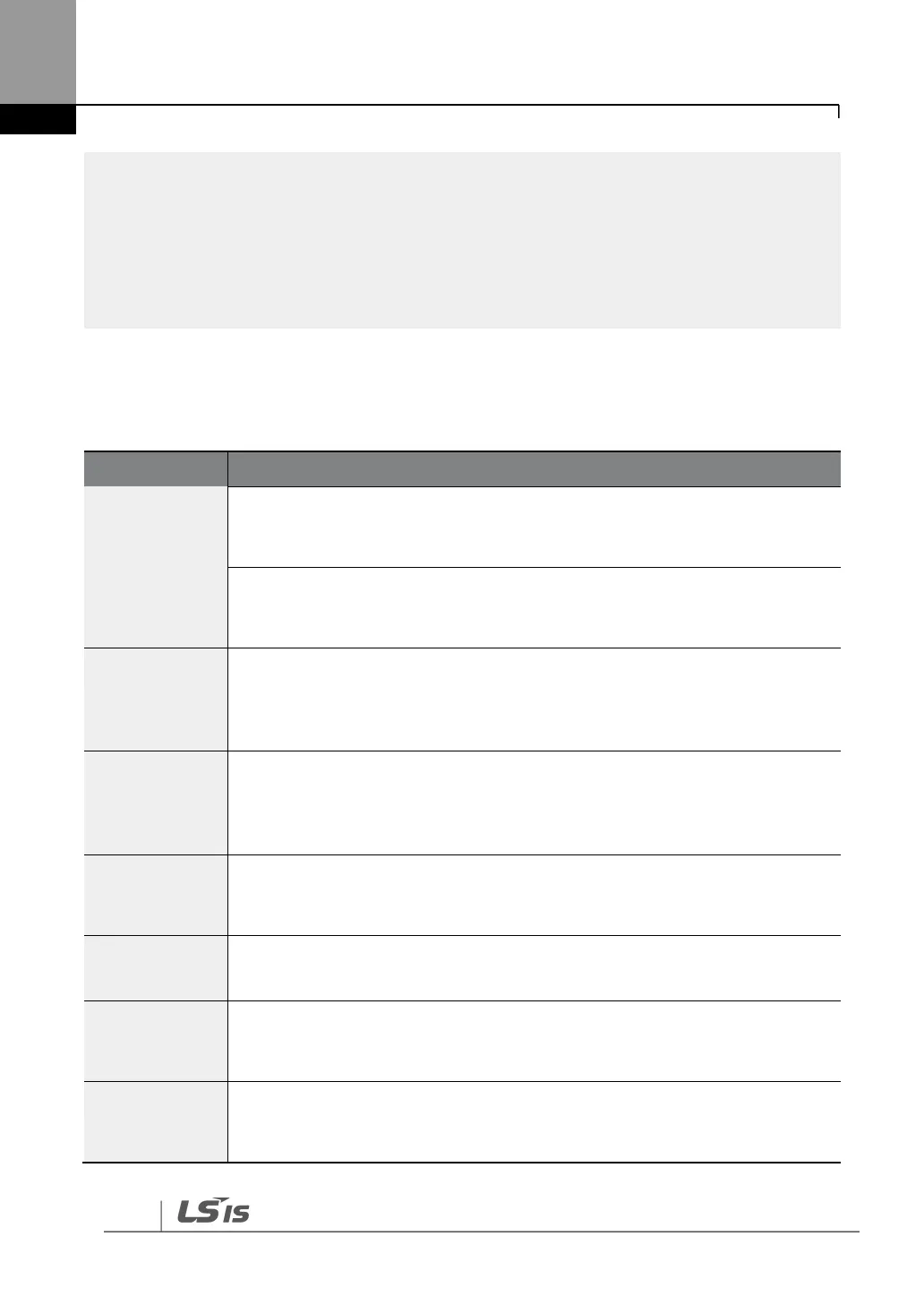
Warning Messages
Displayed when the motor is overloaded. Operates when PRT-17 is set to “1”. To
operate, select “4 (Over Load)”. Set the digital output terminal or relay (OUT31-
33) to “4 (Over Load)” to receive overload warning output signals.
Displayed when the motor is underloaded. Operates when PRT-25 is set to “1”.
Set the digital output terminal or relay (OUT31-33) to “6 (Under Load)” to receive
underload warning output signals.
Displayed when the accumulated overload time is equivalent to 60% of the
inverter overheat protection (inverter IOLT) level. Set the digital output terminal
or relay (OUT31-33) to “5 (IOL)” to receive inverter overload warning output
signals.
The Lost Command warning alarm occurs even when PRT-12 is set to “0”. The
warning alarm occurs based on the condition set at PRT-13-15. Set the digital
output terminal or relay (OUT31-33) to “12 (Lost Command)” to receive lost
command warning output signals.
Displayed when an error is detected from the cooling fan while PRT-79 is set to
“1”. Set the digital output terminal or relay (OUT31-33) to “8 (Fan Warning)” to
receive fan warning output signals.
Displayed when the DB resistor usage rate exceeds the set value. Set the
detection level at PRT-66.
Displayed when “3 (Enc Test)” is set at BAS-20 (Auto Tuning) and no signal is
input during the encoder test. Set the ENC Tune at OUT31–33 to release a
signal.
Displayed when “3 (Enc Test)” is set at BAS-20 (Auto Tuning) and the settings for
A and B encoder phases are changed or are the opposite during the encoder
test. Set the ENC Dir at OUT31-33 to release a signal.

 Loading...


