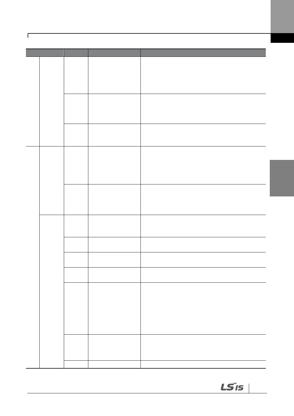
Voltage input for
frequency reference
Used to setup or modify a frequency reference via
the analog voltage input terminal.
Unipolar: 0–10 V
Bipolar: -10–10 V
Input resistance 20 kΩ
Current input for
frequency reference
Used to setup or modify a frequency reference via
the current input terminals.
Input current: DC 0–20 mA
Input resistance 249 Ω
Frequency setting
common terminal
Common terminal for analog voltage and current
terminals (CM common terminal is used for
terminal inputs only).
Multi-function
analog voltage
output terminal
Used to send inverter output information to
external devices.
Output voltage: 0–10 V
Maximum output voltage: 10 V
Maximum output current: 10 mA
Multi-function
analog current
output terminal
Used to send inverter output information to
external devices.
Output current: 4–20 mA (0–20 mA)
Maximum output current: 20 mA
Multi-function
terminal (open
collector)
Common terminal
for open collector
Common ground contact for an open collector
(with external power source).
External 24 V power
source
Maximum output current: 150 mA
Common ground contact for the external 12 V
power source.
Sends out alarm signals when the inverter’s safety
features are activated (below AC 250 V 5 A,
DC 30 V 5 A).
Fault condition: A1 and C1 contacts are connected
(B1 and C1 open connection)
Normal operation: B1 and C1 contacts are
connected (A1 and C1 open connection)
Multi-function
relay2 output A
contact
Outputs the signal while running. User defined
multi-function output terminal.
(< AC 250 V, 5 A / < DC 30 V, 5 A)
Used to send or receive RS-485 signals.