REPAIR INSTRUCTIONS, PART 1
Page 163
Coolant Manifold Removal
[215 NK]
Refer to Figure 153.
1. Disconnect the wires to the dash gauge and
V-MAC III coolant temperature sensors, and
boost air temperature sensor as applicable.
Position the wires out-of-way.
2. Support the coolant manifold assembly and
remove the 12 flangehead capscrews
retaining the assembly to the cylinder heads.
3. Remove the manifold assembly. It may be
necessary to pry or tap lightly with a soft
mallet on the housing to break the seal.
4. If the coolant manifold is to be replaced,
remove the sensor(s) located on the
manifold.
153
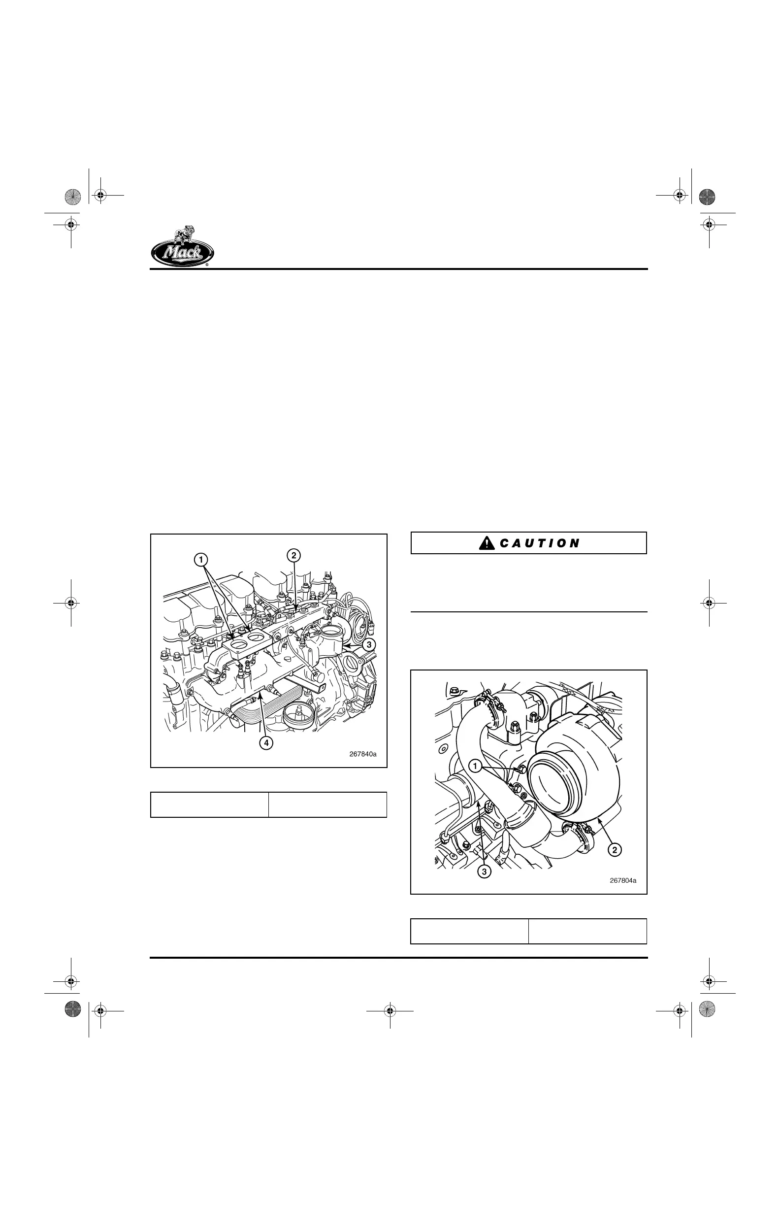
Figure 153 — Coolant and Inlet Manifolds
Air Inlet Manifold Removal
[214 HD]
Refer to Figure 153.
1. Support the air inlet manifold and remove
the 12 capscrews that secure the manifold to
the cylinder heads.
2. Remove the air inlet manifold. It may be
necessary to gently pry or tap the manifold
lightly with a soft mallet to break the seal.
3. If the air inlet manifold is to be replaced,
remove the inlet manifold temperature
sensor located on the inlet manifold, if
installed.
Turbocharger Removal
[214 SD]
Refer to Figure 154.
1. Remove the two capscrews securing the
lubrication drain tube to the turbocharger.
2. Remove the two capscrews securing the
drain tube to the cylinder block and remove
the tube.
The turbocharger is heavy, weighing
approximately 76 lbs. DO NOT attempt to remove
or install the turbocharger without the help of an
assistant or the use of a suitable lifting device.
3. Loosen the four nuts from the turbocharger
mounting studs and remove the
turbocharger from the exhaust manifold.
154
Figure 154 — Turbocharger Mounting
1. Thermostat Ports
2. Coolant Manifold
3. Mixer Tube Mounting
4. Inlet Manifold
1. Retaining Nuts (4)
2. Turbocharger Assembly
3. Exhaust Manifold (Center
Section)
5-111.bk Page 163 Monday, July 10, 2006 2:26 PM