REPAIR INSTRUCTIONS, PART 2
Page 401
FINAL ASSEMBLY
Complete the procedure by installing the radiator,
charge air cooler and hood and fender assembly,
etc. Fill the cooling system and reconnect the
batteries.
Coolant Conditioner Adapter
Removal and Installation
[215 LD]
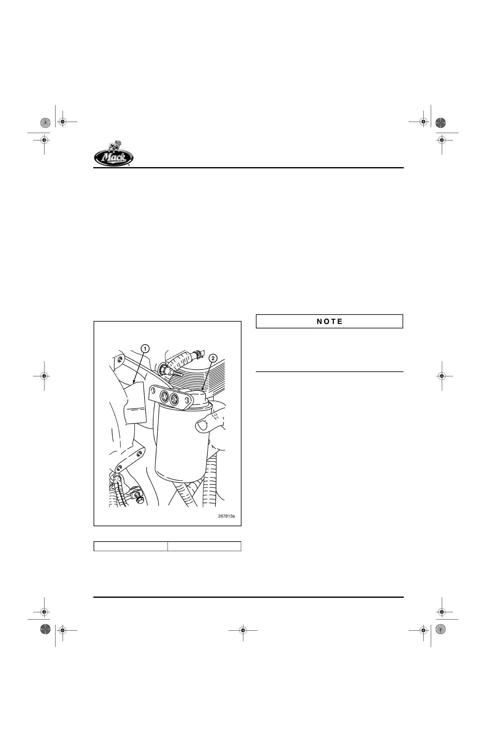
The coolant conditioner adapter (if so equipped)
is located at the left rear side of the water pump
housing. An external conditioner inlet (supply)
tube port is not used. The unit has both inlet and
outlet ports in the water pump mounting flange
(Figure 482).
482
Figure 482 — Conditioner Adapter Installation
1. Place a suitable container below the coolant
filter area to catch any spilled coolant.
2. Using a suitable filter wrench, J 29927 or
equivalent, remove the coolant conditioner
filter element. Discard the element.
3. Remove the adapter assembly from the
water pump housing by removing the two
mounting capscrews.
4. Remove and discard the O-rings at the inlet
and outlet ports.
5. Carefully remove and examine the check
valve assemblies in the inlet and outlet
ports. Check each assembly by depressing
the check ball. If it resists movement and
does not return to its seat freely, the check
valve assembly must be replaced.
Inlet and outlet check valves must be reinstalled
with the direction arrows on the barrels of the
check valves matching the arrows on the filter
casing. If not indexed correctly, the coolant will
not flow through the coolant conditioner.
6. Install new O-rings in the grooves at the inlet
and outlet ports.
7. Place the adapter assembly in position on
the water pump mounting flange and install
the two mounting capscrews. Tighten the
capscrews to 15 lb-ft (20 N폷m).
8. Apply a light film of engine coolant on the
face of the coolant conditioner filter gasket
seal.
9. Install the coolant conditioner filter element
on the adapter. Turn the filter element one
full turn after the gasket contacts the base.
1. Pump Housing 2. Adapter
5-111.bk Page 401 Monday, July 10, 2006 2:26 PM