Page 400
REPAIR INSTRUCTIONS, PART 2
7. Push the housing against the block and
hand-tighten the mid-position mounting bolts
(item 4 in Figure 477).
8. Install the two mounting bolts and washers
in the low-position mounting holes (item 5),
hand-tight.
9. Make sure the lifting bracket mounting holes
are properly positioned on the insert collars
and then tighten the mid-position and
low-position bolts to specification, 69 lb-ft
(94 N폷m), in sequence A, B, C, D shown in
Figure 477.
10. Using a suitable slotted socket, tighten the
two threaded inserts to specification,
50 lb-in (5.6 N폷m).
Use care not to overtighten the threaded inserts.
Doing so could place undue stress on the
housing, causing it to bow and eventually break.
Tighten the insert only to 50 pound-inches.
11. Install the remaining two mounting bolts (no
washers) through the threaded inserts and
tighten to specification, 40 lb-ft (55 N폷m).
12. Position the water pump stiffening bracket
(item 1 in Figure 477) over the two studs at
the forward position of the water manifold. At
the same time, position the forward section
of the stiffening bracket over the backside of
the A/C compressor upper rear mounting
stud. Install the three M8 flanged nuts on the
stiffening bracket and tighten to 20 lb-ft
(27 N폷m). Refer to Figure 477.
It is important not to install the stiffening bracket
before the water pump housing fasteners have
been torqued in place. Installing the bracket
before the housing bolts have been tightened
may put undue stress on the top of the housing
and cause damage to the housing.
13. Connect the coolant inlet tube from the oil
cooler to the inlet port at the back of the
water pump on the left side of the engine.
14. Connect the EGR cooler coolant supply
hose to the water pump on the right side of
the engine.
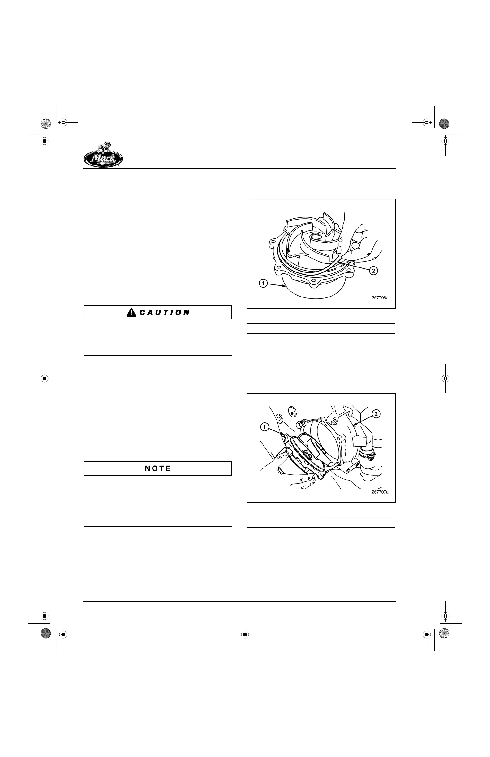
15. Install a new O-ring on the pump cartridge
housing mounting flange (Figure 480).
480
Figure 480 — O-Ring Installation
16. Place the pump cartridge assembly in
position on the pump housing (pump only fits
one way due to the spacing of the seven
holes) and install the seven mounting
capscrews (Figure 481). Tighten the
capscrews to 17 lb-ft (23 N폷m).
481
Figure 481 — Water Pump Cartridge
17. Install the fan drive assembly, drive belts
and connect the fan-speed sensor lead.
1. Water Pump Cartridge 2. O-Ring
1. Water Pump Cartridge 2. Water Pump Housing
5-111.bk Page 400 Monday, July 10, 2006 2:26 PM