Page 180
REPAIR INSTRUCTIONS, PART 1
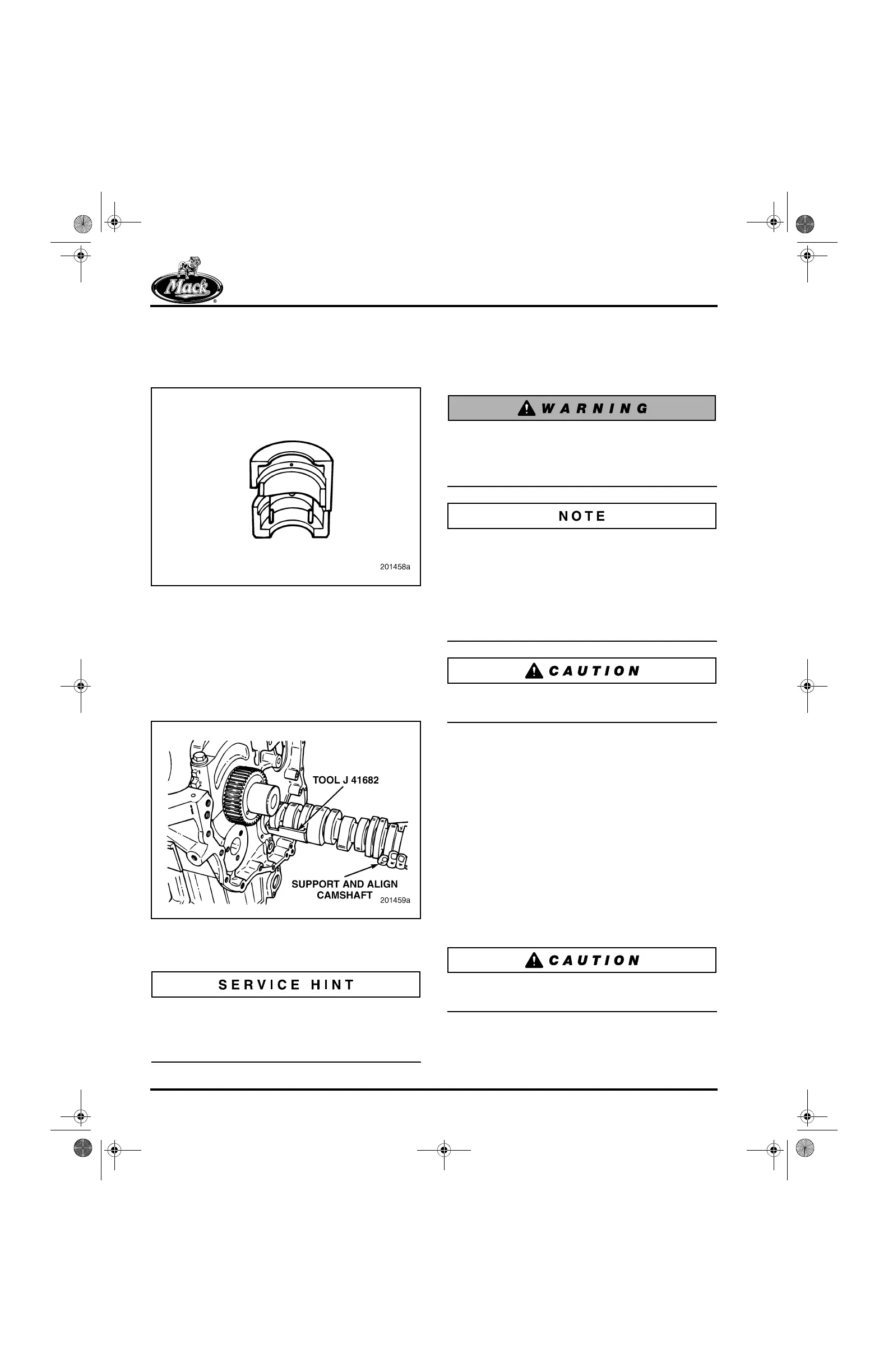
4. Install the camshaft removal/installation tool
J 41682 (Figure 178) in position on the rear
segment of the camshaft, securing it to the
shaft with the clip.
178
Figure 178 — Camshaft Installation Guide
5. Taking care not to damage the camshaft or
bushings, pull the camshaft out from the
front of the engine (Figure 179). Carefully
guide the rear of shaft through the journals.
If the shaft does not come out freely, ensure
that all valve lifters are clear of camshaft
lobes and journals.
179
Figure 179 — Camshaft Removal
6. Remove the valve lifters.
Valve lifters have established wear patterns and
should be reinstalled in the same locations. Label
each valve lifter upon removal and place on a
clean work surface.
Piston and Connecting Rod
Assembly Removal
[212 NP, LQ]
The crankshaft and related components are
heavy, have sharp edges and many possible
pinch points. Always be careful while working
in this area to avoid serious personal injury.
Before removing the pistons, connecting rods and
rod caps, ensure that they are tagged for
reinstallation in the same cylinders from which
removed.
Remove the connecting rod and piston
assemblies in companion cylinder sets: 1 and 6, 2
and 5, and 3 and 4.
Do not stamp or engrave on the TOP of the
piston. Doing so will reduce piston life.
1. Rotate the engine 90 degrees on the stand
so that the pistons lie horizontally in the
block with the top of the pistons and
connecting rods accessible from the sides.
2. Rotate the crankshaft so that pistons 1 and 6
are lowered in the cylinder at least 2 inches
(51 mm) to allow adequate room to remove
carbon from the upper edge of the sleeves.
3. Using a sharp knife, carefully remove any
carbon at the top of the sleeves
(Figure 180). Remove any remaining carbon
using crocus cloth or fine sandpaper. Then
wipe the inside of the sleeves with a clean
cloth.
Use care not to damage the cylinder sleeve when
removing the carbon buildup.
5-111.bk Page 180 Monday, July 10, 2006 2:26 PM