REPAIR INSTRUCTIONS, PART 1
Page 353
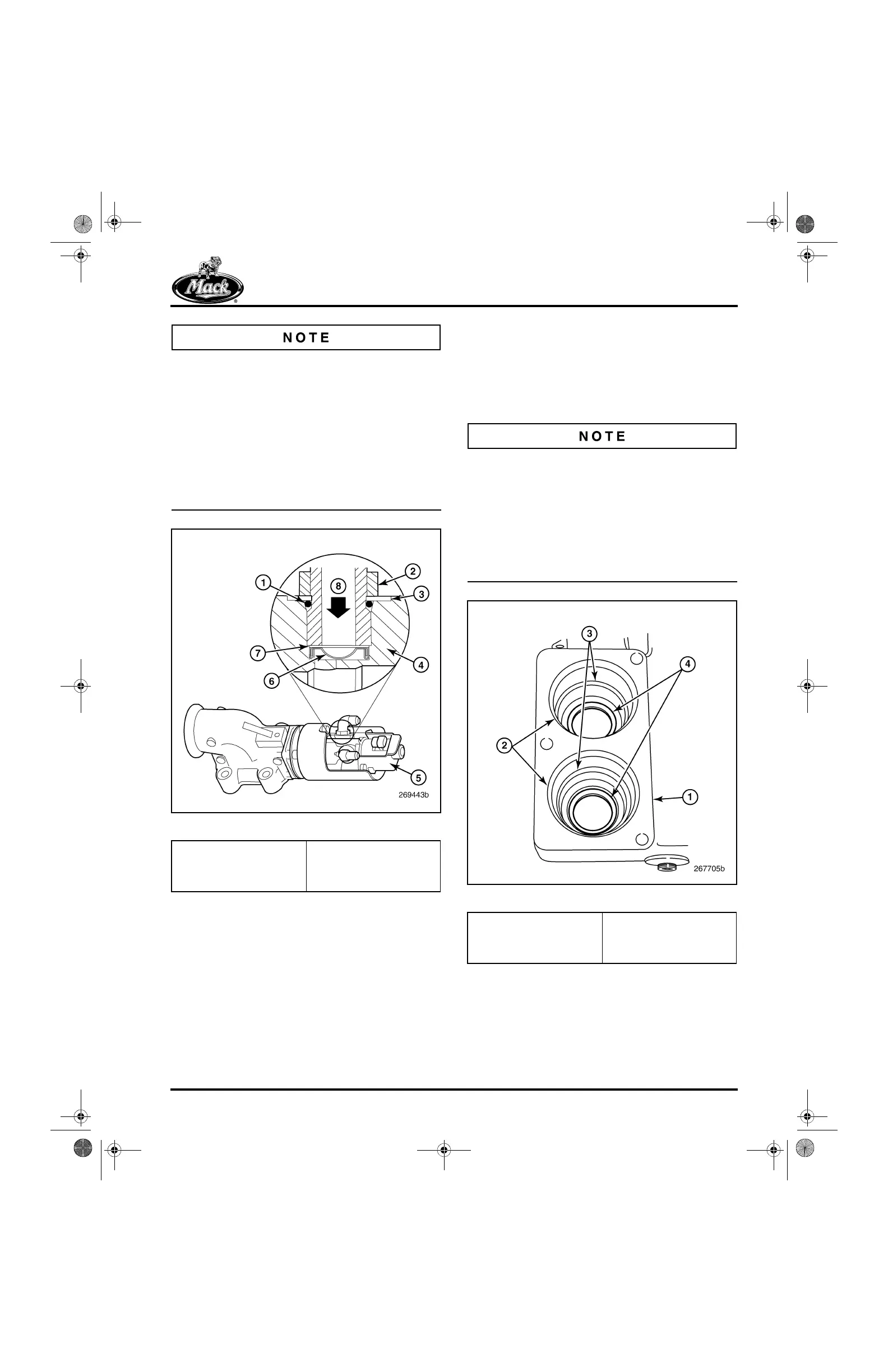
Beginning with March 2004 production, a filter
screen has been added to the oil inlet port on the
EGR valve. It is retained in place by a wave
washer and inlet hose fitting (Figure 419). Valves
fitted with the filter screen are identified by a
green dot (interim identification) on the valve
body or by the new part number, 691GC514C, on
the sheet metal cover. When connecting the oil
line to the EGR valve, make sure that the screen
and wave washer are in place and secured by the
hose fitting.
419
Figure 419 — EGR Valve Oil Inlet Filter Screen
4. Position the turbocharger oil supply line over
the top of the engine and in between the
cylinder heads.
5. Reconnect the oil supply line from the oil
filter adapter to the turbocharger oil supply
by routing the oil supply line between the
cylinder heads and reconnect the line to the
turbocharger oil inlet fitting and tighten to
specifications.
Thermostat Housing Installation
[215 NU, NG & LD]
1. Check to see that the stainless steel wear
rings/shields are properly installed in the
thermostat housing (Figure 420).
If the wear rings/shields are not in place, the
thermostats can wear into the aluminum casting
of the thermostat housing. If the wear
rings/shields become dislodged or out of position,
they can be replaced, or if necessary, crimped to
attain a tight fit, and then reinstalled. The shields
have a very slight press-fit to the bore. An
installation tool is not used. Use finger pressure
to push each shield to full seating.
420
Figure 420 — Wear Rings Installed
1. O-Ring
2. Fitting Jam Nut
3. Integral Washer
4. Valve Body
5. Part Number Location
6. Filter Screen
7. Wave Washer
8. Oil Flow Direction
1. Thermostat Housing
2. Thermostat Rubber Seal
Bore
3. Thermostat Barrel Seal
Bore
4. Wear Rings/Shields
(Pressed In)
5-111.bk Page 353 Monday, July 10, 2006 2:26 PM