DESCRIPTION AND OPERATION
Page 67
Crankshaft
The crankshaft is fully counterbalanced and has
induction-hardened journals. It is supported with
main bearings at seven locations. Thrust washers
are located at the center main bearing (position
No. 4) to absorb fore and aft end thrust.
At the forward end of the crankshaft is an
extension that carries the main drive gear,
vibration damper and accessory drive pulleys.
The main drive gear is keyed to the crankshaft,
ensuring proper assembly and engine timing. At
the rear of the crankshaft is a flange for mounting
the flywheel. Two seals, one each at the front and
rear journals of the crankshaft, prevent lubricating
oil leaking from the engine.
Webs cast into the crankcase provide the upper
main bearing supports for the crankshaft.
Removable bearing caps retained with
capscrews provide the lower bearing supports
and proper alignment for the crankshaft. The
bearing caps are not interchangeable and each
has a number stamped on it which signifies its
correct location and alignment in the crankcase.
The caps are numbered 1 through 7, with the
No. 1 main bearing cap at the front of the engine.
The bearing inserts are precision-designed, and
are positioned between the crankshaft and
crankcase, and between the crankshaft and the
bearing caps. Thrust flanges to support the thrust
washers are located at the center main bearing
(No. 4).
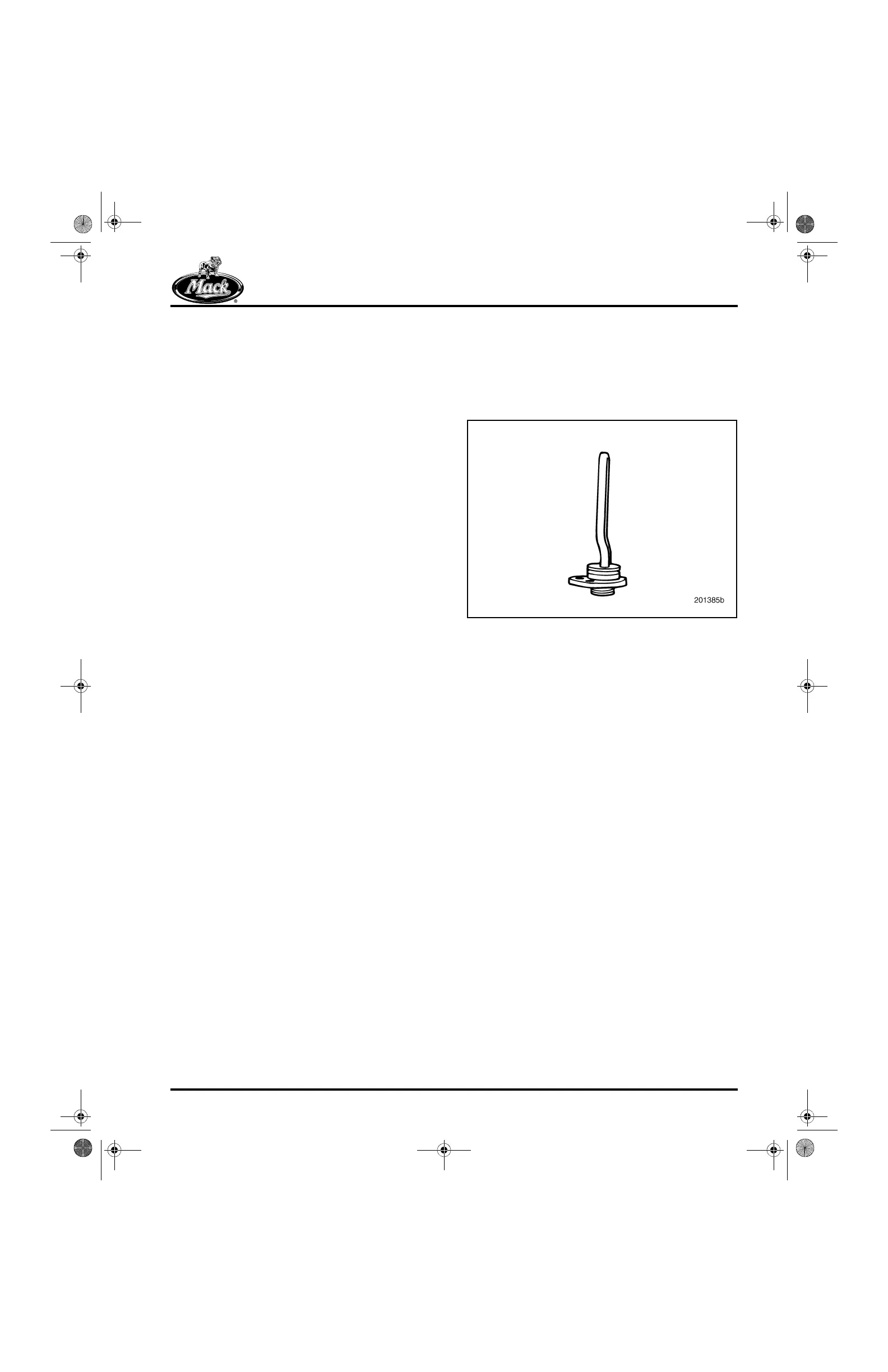
Block Heater
The engine accepts a straight element unit in the
rear location. Effective with ASET™ engine
introduction, all factory installations use the rear
location only.
76
Figure 76 — Straight Block Heater
5-111.bk Page 67 Monday, July 10, 2006 2:26 PM