Page 362
REPAIR INSTRUCTIONS, PART 1
8. Connect the wiring harness to the EECU
(Figure 437).
Make sure that the seals are firmly seated on the
connectors and that the EECU terminal pins are
straight and not damaged.
앫
EJ2 (89-pin connector) — Lift the locking
lever to the full-open position and place the
connector in position squarely over the
module terminals. Push the connector into
the module until firmly seated. Then, close
the locking lever to secure the connection.
DO NOT use the locking lever to seat the
connector.
앫
EJ1 (36-pin connector) and EJ3 (16-pin
connector) — Lift the metal locking lever to
the full-open position and place the
connector in position squarely over the
module terminals. Push the connector into
the module until firmly seated. And last,
push down on the center crosspiece of the
lever to close and secure the connection.
DO NOT apply pressure to the outer edges
of the locking lever which then can be bent
and fail to secure the connection.
437
Figure 437 — EECU Connectors
Place the harness retainer in position on the
support bracket and install the retaining screw.
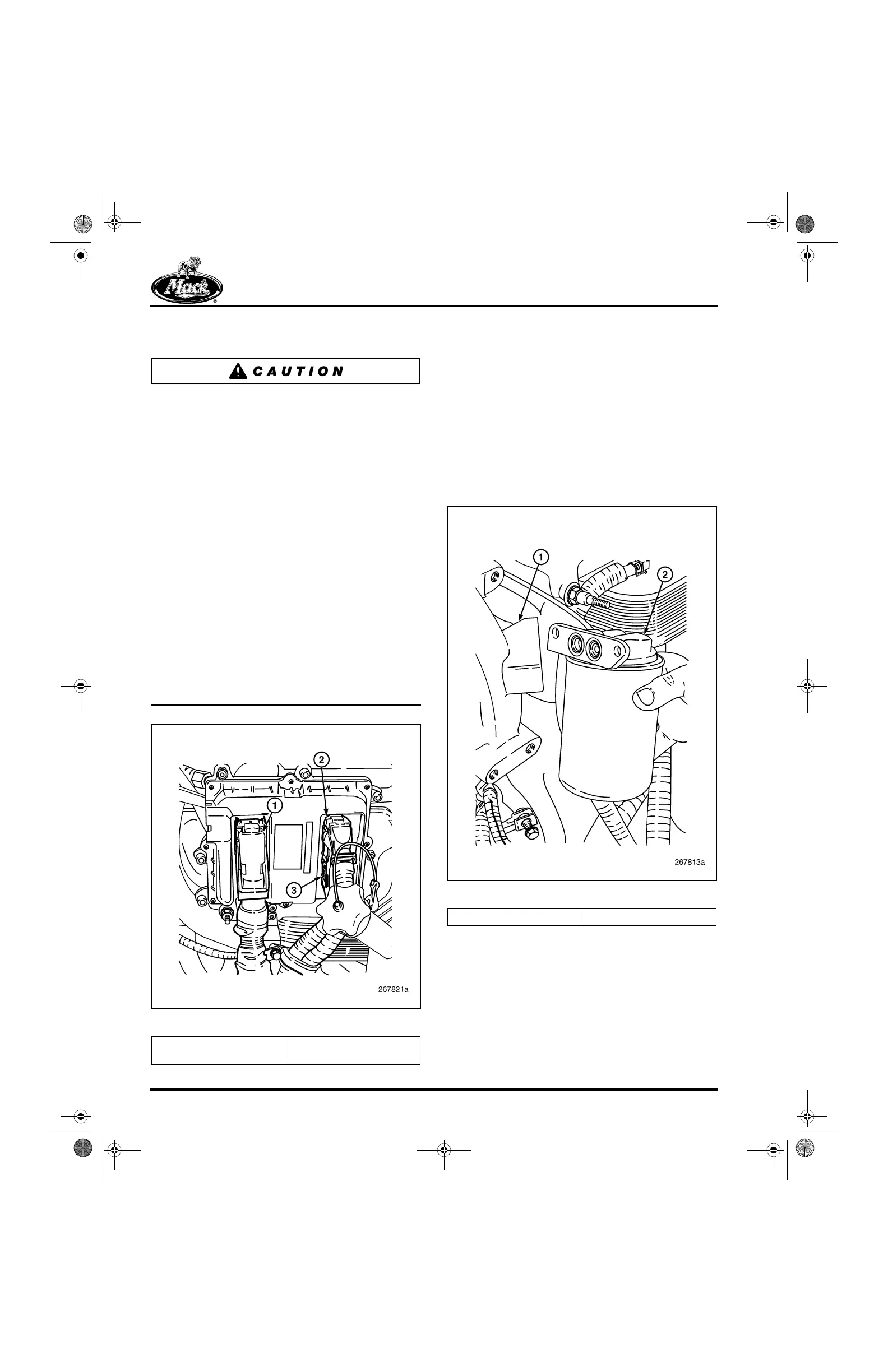
Coolant Conditioner Installation
[215 LD]
The coolant conditioner adapter (if equipped) is
located at the left rear side of the water pump
housing. The adapter has both inlet and outlet
ports in the water pump mounting flange
(Figure 438).
438
Figure 438 — Conditioner Adapter Installation
1. Connector EJ2 (89 Pin)
2. Connector EJ1 (36 Pin)
3. Connector EJ3 (16 Pin)
1. Pump Housing 2. Adapter
5-111.bk Page 362 Monday, July 10, 2006 2:26 PM