Page 378
REPAIR INSTRUCTIONS, PART 2
6. After installing the removal/installation tool
J 41682, remove the idler gear and hub.
Following camshaft installation, it is easier to
remove the camshaft removal/installation tool
J 41682 if the idler gear and hub have been
removed first. For this reason, the idler gear and
hub should be removed at this time.
7. Taking care not to damage the camshaft or
bushings, pull the camshaft out from the
front of the engine. Carefully guide the rear
of the shaft through the journals. If the shaft
does not come out freely, ensure that all
valve lifters are clear of the camshaft lobes
and journals.
8. Remove and inspect the valve lifters.
Valve lifters have established wear patterns and
should be reinstalled in the same locations. Label
each valve lifter upon removal and place it on a
clean work surface.
Cleaning and Inspection of Cylinder
Block
Salvaging a Damaged Valve Lifter Bore
Refer to “SALVAGING A DAMAGED VALVE
LIFTER BORE” on page 189 for complete valve
lifter bore repair criteria.
Salvaging a Damaged EUP Tappet Bore
Refer to “SALVAGING A DAMAGED EUP
TAPPET BORE” on page 188 for complete EUP
tappet bore repair criteria.
Cylinder Block Cleaning and Lifter Checks
While the camshaft is removed and lifter bores
are relatively accessible, it is a good practice to
clean all the lifter bores and then trial-fit all the
lifters into their respective bores and H-rings.
Clean and trial-fit lifters as follows:
1. Clean all lifter bores with a fresh supply of
suitable brake/parts cleaner. Ensure all
Loctite
®
residue and dried contamination
has been removed.
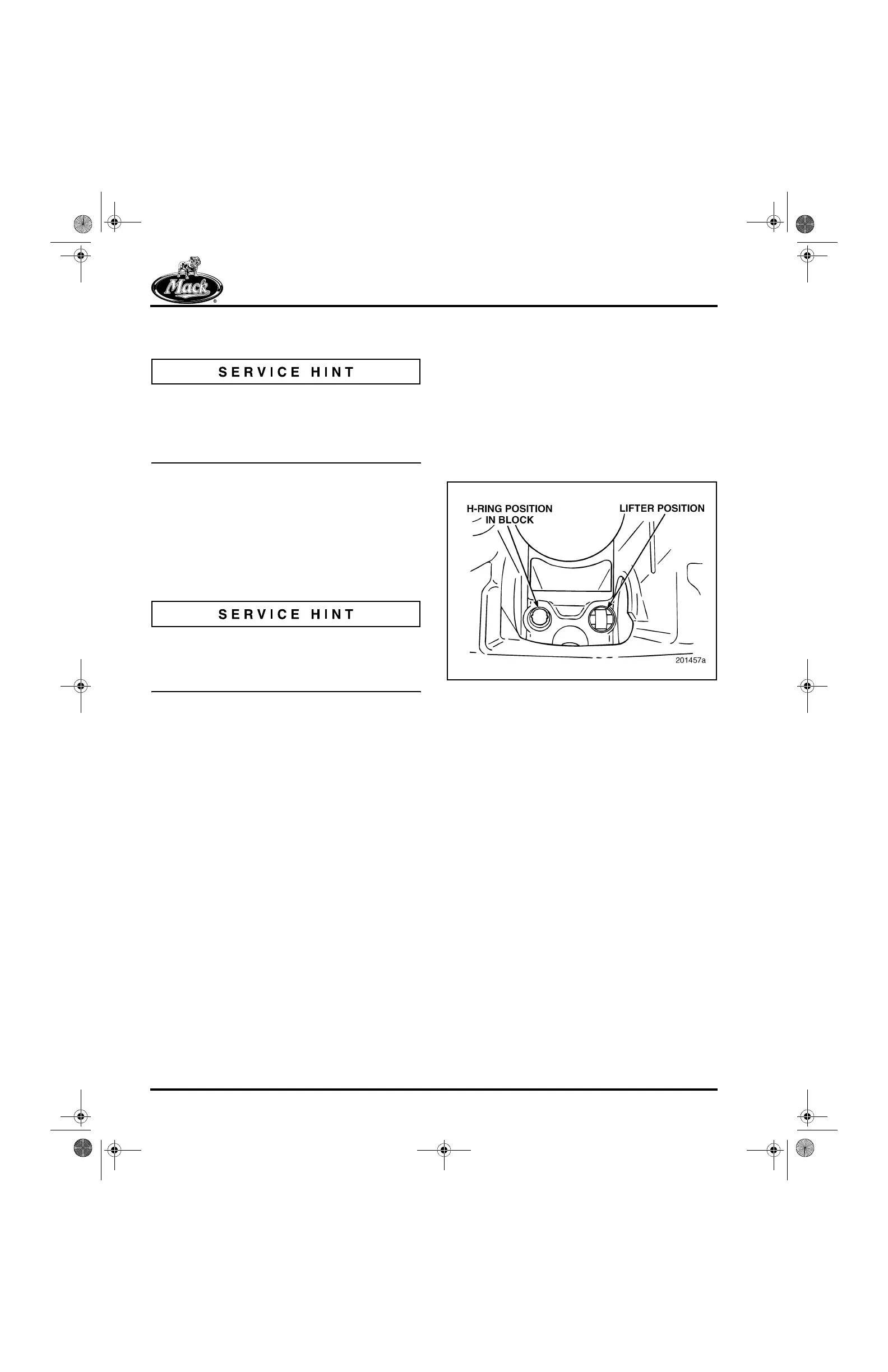
2. Trial-fit a lifter back into its original lifter bore
by aligning the lifter flats with the H-ring flats
as shown in Figure 453. Use only light finger
pressure when installing the lifters. Verify
that the lifter has complete freedom of
movement in the bore and H-ring in both the
upward and downward directions. When the
lifter is seated, it should be possible to rotate
it slightly from left to right. If the lifter is sticky
or tight, or if additional force was required to
install the lifter, proceed as follows:
453
Figure 453 — Installed Valve Lifter
a. If new lifters are being installed and the
fit is tight, try the lifter in another lifter
bore. A stack-up of component
tolerances can result in a lifter being
free in another bore. This is acceptable.
b. If the original lifters are being reused
and the fit is tight, trial-fit a new lifter(s)
in the bore. If the tightness persists, the
problem may be in the lifter bore or
H-ring. (Because of established wear
patterns, it is not recommended to
install a used lifter in any bore other
than the bore from which it was
removed.)
c. If the problem is confined to a particular
bore, determine if the lifter tightness is
due to the lifter bore or the H-ring by
trial-fitting another lifter. To correct the
problem condition, refer to the
procedure under “Salvaging a Valve
Lifter Bore” or “H-Ring Replacement” in
the CYLINDER BLOCK
RECONDITIONING section.
5-111.bk Page 378 Monday, July 10, 2006 2:26 PM