Page 254
REPAIR INSTRUCTIONS, PART 1
Inlet and Exhaust Valve Installation
For identification purposes, the exhaust valve has
two stem grooves in addition to the valve spring
keeper groove; whereas, the inlet valve has one
stem groove in addition to the spring keeper
groove.
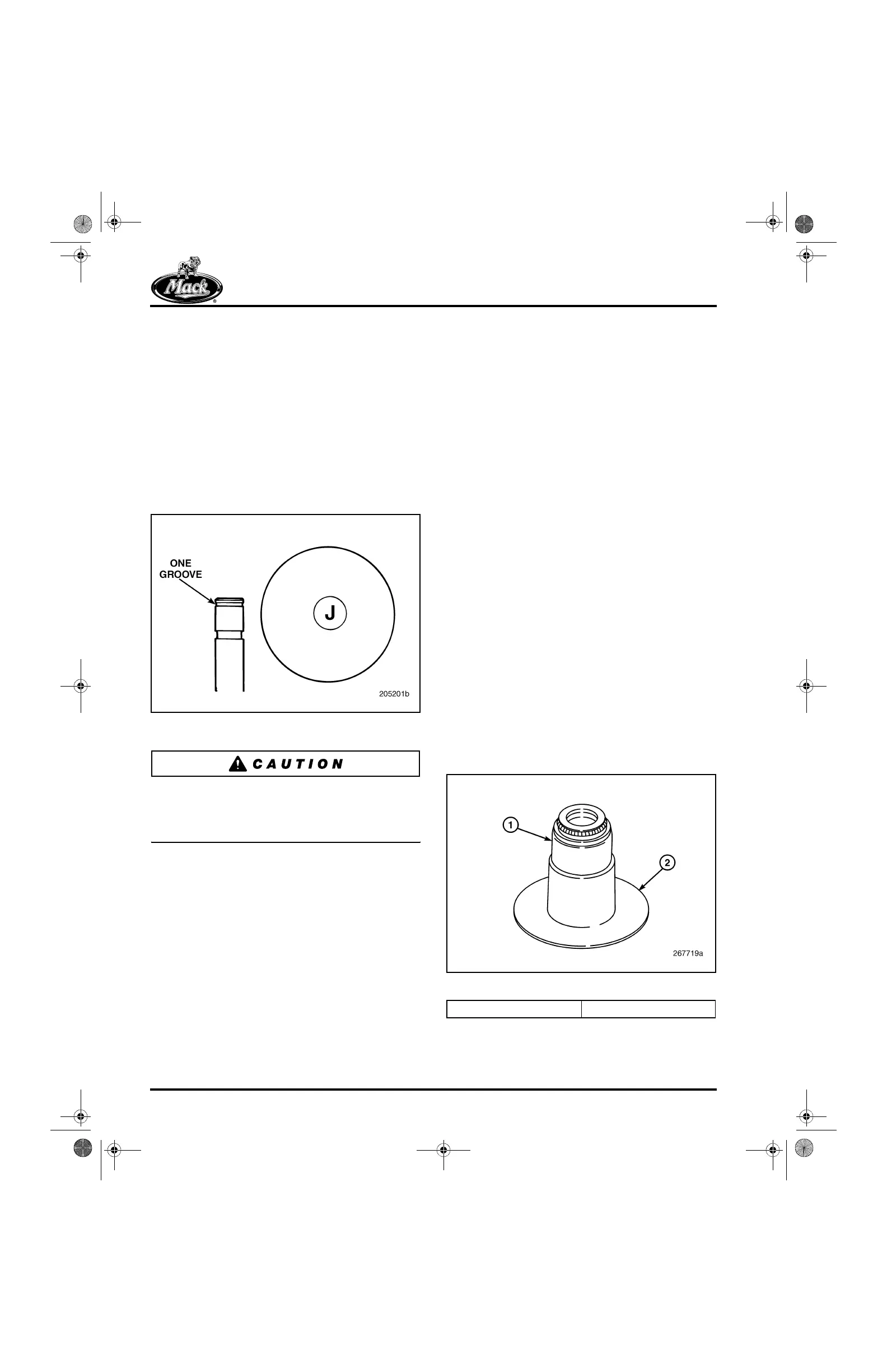
The valves are also identified by the letter “J”
(20-degree inlet), and letters “EX” (exhaust), on
the bottom face of the valve head. Refer to
Figure 278 for an illustration of the inlet valve
identification.
278
Figure 278 — 20-Degree Intake Valve Identification
The inlet and exhaust valve head diameters are
nearly the same size. It is important, therefore,
that extra care be taken when installing these
valves.
1. Lubricate the inside diameter of the valve
guides by using a “bottle brush” coated with
Dow Corning
®
BR2 Plus multipurpose
grease. This is particularly important when
both the valves and the valve guides are
new. (With an on-engine seal replacement,
pre-lube the valve stems with clean engine
oil while moving the valve up and down,
prior to installation of the valve spring.)
2. With these new valve stem seals,
pre-lubrication during installation is
extremely important. Pre-lubricate the seals
as follows:
앫 Valve Stem-to-Guide — Lubricate the
inside diameter of the valve guides by
using a “bottle brush” coated with
graphite grease. This is particularly
important when both the valves and the
guides are new. With an on-engine seal
replacement, pre-lubricate the valve
stems with clean engine oil while
moving the valve up and down before
installing the valve spring(s).
앫 Valve Stem-to-Seal Lip — The inside
diameter of the seal lip and outside
diameter of the valve stem should be
well-lubricated with clean engine oil
when installing the seal over the valve
stem.
3. Early Design Valve Guide and Stem Seal
A combination valve spring seat and integral
stem seal was used on the first 200 ASET™
engines. This early design seal is no longer
available. Engines built with this seal
arrangement will need to be converted to the
current configuration multi-lip type seal. This
conversion will require the replacement of
the valve guides to the current configuration.
Refer to “Valve Guide Replacement” earlier
in this section.
279
Figure 279 — Valve Stem Seal (Early Design)
1. Valve Stem-to-Seal Lip 2. Valve Stem Seal
5-111.bk Page 254 Monday, July 10, 2006 2:26 PM