DESCRIPTION AND OPERATION
Page 53
With the J-Tech™ engine brake, the standard
ASET™ engine valve yokes are used at both inlet
and exhaust locations. However, a hollow yoke
adjusting screw with a floating pin in the screw is
used in the exhaust yokes (Figure 53). The screw
opens only the exhaust valve directly beneath it
when the engine brake is activated. In addition,
the exhaust rocker arm adjusting screws and nuts
(Figure 55) are unique for the J-Tech™ engine
brake application.
55
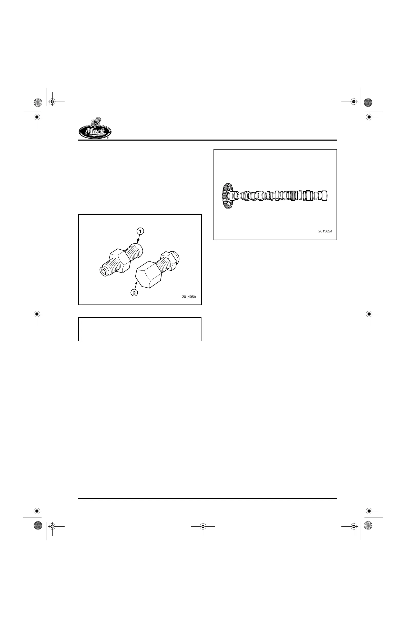
Figure 55 — Rocker Arm Adjusting Screws and Nuts
Camshaft
The camshaft (Figure 56) is machined with lobes
for actuating the unit pumps and the inlet and
exhaust valves. The large diameter of the
camshaft provides the additional strength needed
for operating the unit pumps as well as the valve
train. Journals and lobes are induction-hardened
by a process that produces a pronounced heat
discoloration mark approximately 3/8-inch wide,
around the front and rear faces of each journal
and lobe.
Other notable features of the camshaft include a
bump in the exhaust cam profile that provides
timing for engine brake operation. There is also a
groove in the No. 4 journal to aid in reducing cam
bushing temperature.
56
Figure 56 — Camshaft
Valve Train
ROLLER LIFTERS/FOLLOWERS
Roller lifters and roller followers or “tappets” are
used to actuate the valves and unit pumps,
respectively. The roller aspect of these
assemblies handles aggressive cam profiles
better and has increased load-carrying capability.
The roller lifters are held in alignment by H-rings
pressed into the lifter bores; whereas, the EUP
roller followers are held in alignment by the tappet
guide pins pressed into the cylinder block.
The current redesigned roller lifter has two longer
lands that provide more bearing area than the
previous design, and the lifter body is now made
of hardened steel for greater scuff resistance
(Figure 57). The bronze axle used in the previous
design has been replaced with a steel axle having
a smaller diameter for optimization of roller and
axle sizes. The pressure oil feed hole to the axle
has been eliminated and replaced with oil
grooves on the inside of the lifter legs. The lifter
roller is composed of a ceramic material
specifically designed for use in engine
components.
When handling ceramic roller lifter assemblies,
care must be taken to avoid damage. If a lifter
having a ceramic roller is dropped, cracks that
are too small to detect may be present and result
in failure of the ceramic roller. DO NOT use a
ceramic roller lifter that has been dropped.
1. Standard Rocker Arm
Adjustment Screw and
Nut
2. Special Screw and
Spherical Jam Nut
(J-Tech™ Exhaust
Position Only)
5-111.bk Page 53 Monday, July 10, 2006 2:26 PM