Page 54
DESCRIPTION AND OPERATION
57
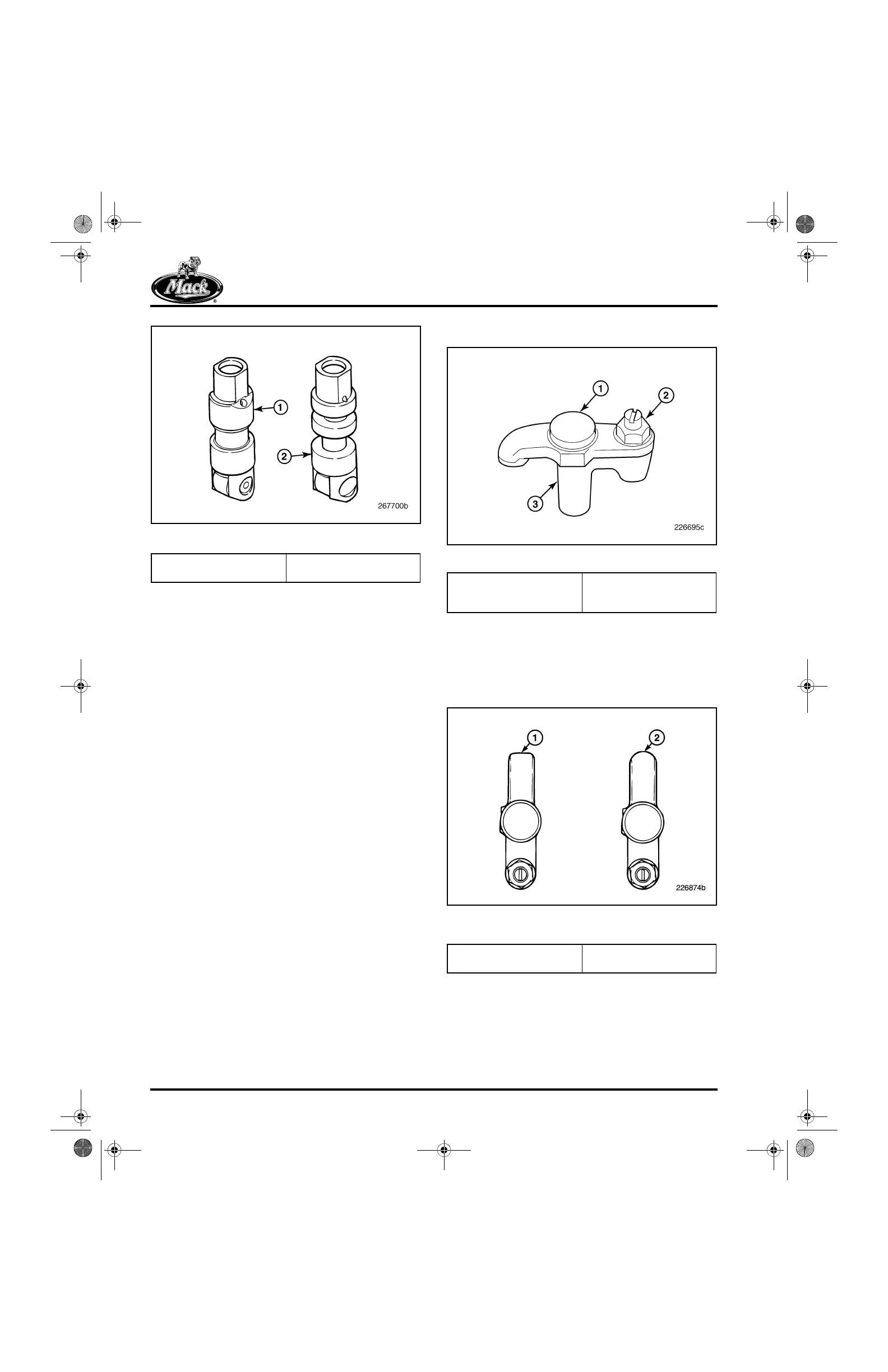
Figure 57 — Roller Lifters
VALVES
The stem tip of the valve has grooves to identify
the valve as intake or exhaust. The intake valve
has one stem groove in addition to the valve
spring keeper groove; the exhaust valve has two.
Seat face angles are also different, 20 degrees
for the intake and 30 degrees for the exhaust.
YOKES
Pinless valve yokes are used for the inlet valves
(with standard push rods), and non-brake
exhaust valves (with spring-loaded push rods).
The spring-loaded push rods have made it
possible to use pinless valve yokes at the
exhaust locations on non-brake engines. As a
result, valve yoke guide pins at the inlet and
non-brake exhaust valve locations have been
eliminated from the cylinder heads.
AC engines equipped with an engine brake have
pin-type yokes at the exhaust valve locations and
pinless yokes at the inlet valve locations. Both are
made of ductile iron and have a button-style wear
pin at the point of rocker arm engagement.
Significant dimensional changes and
modifications have occurred in valve yoke design
over the years. As a result, it is important that the
correct valve yokes are used in all service work.
The following will help in identifying the correct
parts to use.
Pin-Type Yoke
58
Figure 58 — Current Valve Yoke
The most positive method of identification is to
look at the nose of the valve yoke.
ASET™/E-Tech™ valve yokes have the nose
end of the slipper pad area ground flat as shown
in Figure 59.
59
Figure 59 — ASET™/E-Tech™ and E7 Valve Yokes (Top
View)
1. Current Ceramic Roller
Lifter
2. Non-Current Steel Roller
Lifter
1. Headed Pin
2. Adjusting Screw and Jam
Nut
3. Valve Yoke
1. Flat Ground Nose
(ASET™/E-Tech™)
2. Rounded Nose (E7 Only)
5-111.bk Page 54 Monday, July 10, 2006 2:26 PM