DESCRIPTION AND OPERATION
Page 55
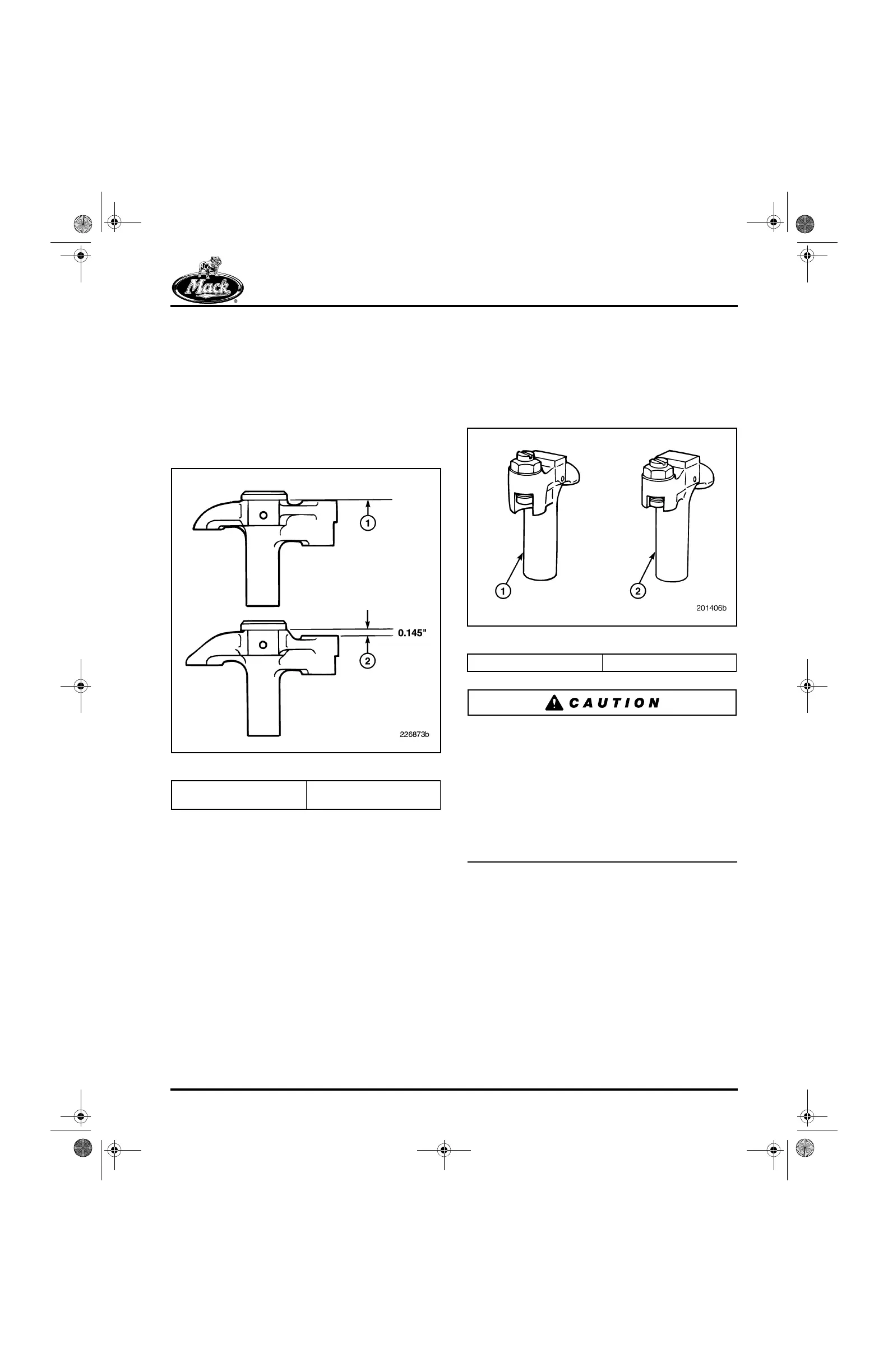
A second method of identifying the “button-head”
yoke is to look at the side view. On the yoke
design used for the ASET™ engines, the top
surface of the adjusting screw end is on the same
plane as the bottom surface of the “button-head.”
On valve yokes used on engine models prior to
ASET™ and E-Tech™, the top surface of the
adjusting screw area is 0.145 inch below the
bottom surface of the “button-head.” Refer to
Figure 60 for an illustration of these differences.
60
Figure 60 — Valve Yoke Side View
The valve yokes used on the ASET™/E-Tech™
engines have a deeper engagement at the yoke
screw end than the yokes used on the E7-PLN
engine, because of the longer valve (Figure 61).
ASET™/E-Tech™ and E7-PLN yokes are very
similar in appearance, but should not be
interchanged.
61
Figure 61 — Valve Yokes
DO NOT interchange yokes. For example, if a
current design yoke from an ASET™ engine is
used on an earlier E7 engine, the valve keepers
will become dislodged and cause a dropped
valve. This will cause severe engine damage. If
the non-current design yoke from an E7 engine is
used on an exhaust location of a J-Tech™
brake-equipped ASET™ engine, the yoke will
disengage from the valve stem tip during engine
brake operation. See Figure 62.
1. Same Plane
(ASET™/E-Tech™)
2. Below (0.145″ for E6, E7
and E9 Only)
1. Current 2. Non-Current
5-111.bk Page 55 Monday, July 10, 2006 2:26 PM