Page 324
REPAIR INSTRUCTIONS, PART 1
Valve Yoke Installation
[213 NV]
GENERAL INFORMATION
There are two exhaust valves and two inlet valves
for each cylinder. Each rocker arm, in conjunction
with the valve yoke, operates both valves
together as a set (exhaust or inlet). It is important
that the correct yokes are used. There are two
ways of identifying the current and non-current
yokes by shape. The current yoke has the nose
end of the slipper pad area ground flat as shown
in Figure 377.
377
Figure 377 — Valve Yoke Comparison (Top View)
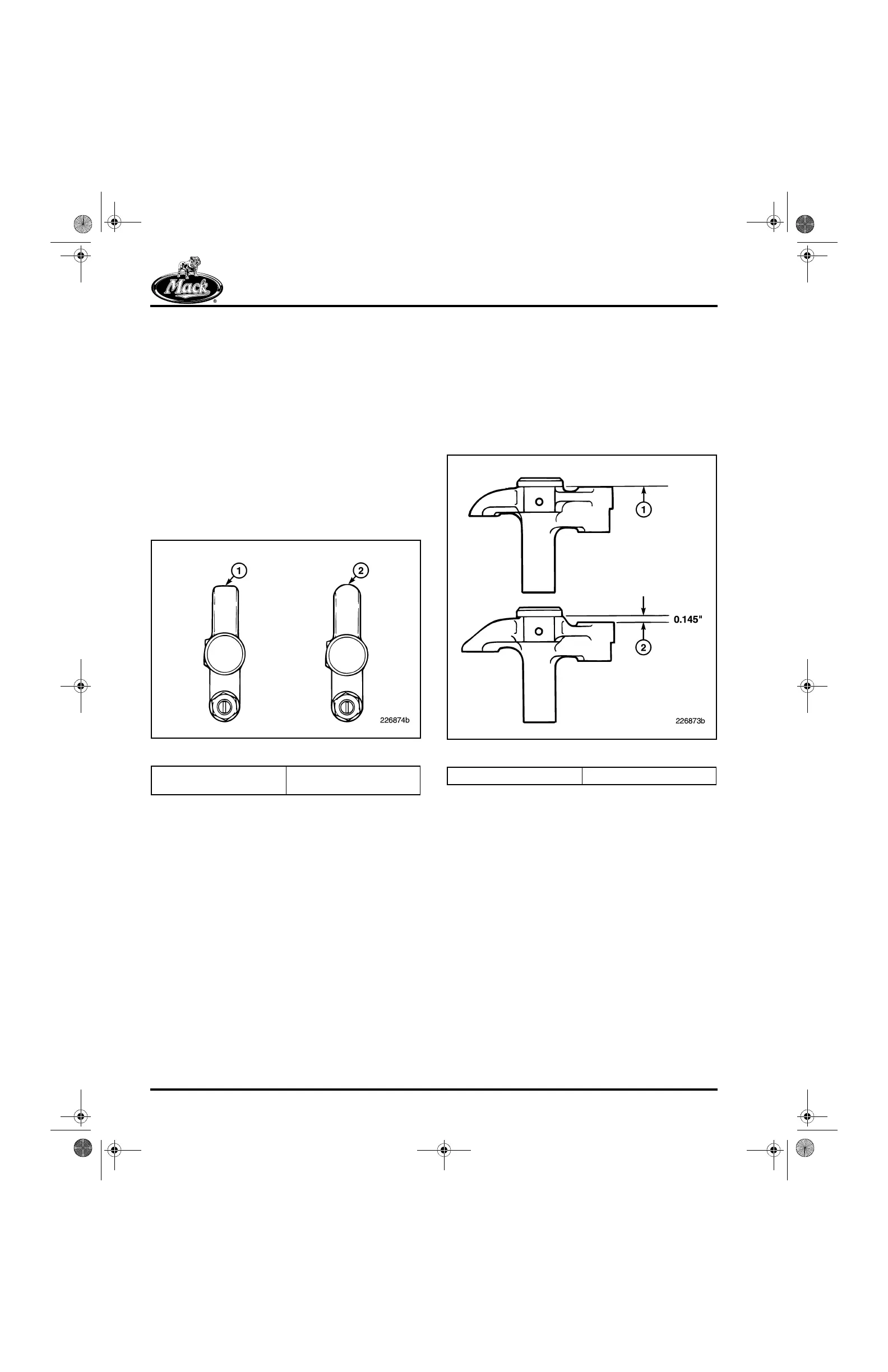
The second method of identifying the valve yoke
is by viewing the yoke from the side. The top
surface of the adjusting screw end will appear on
the same plane as the bottom surface of the
“button-head.” On earlier engine models, the top
surface of the adjusting screw area is 0.145 inch
below the bottom surface of the “button-head.”
Refer to Figure 378 for an illustration of these
differences.
378
Figure 378 — Valve Yoke Side View
1. Flat Ground Nose
(Current)
2. Rounded Nose
(Non-Current)
1. Same Plane (Current) 2. Below (Non-Current)
5-111.bk Page 324 Monday, July 10, 2006 2:26 PM