REPAIR INSTRUCTIONS, PART 1
Page 201
Auxiliary Shaft Bushing
Replacement
[212 CB]
The front and rear auxiliary shaft bushings are
identical. Procedures for inspection and
replacement are as follow:
INSPECTION
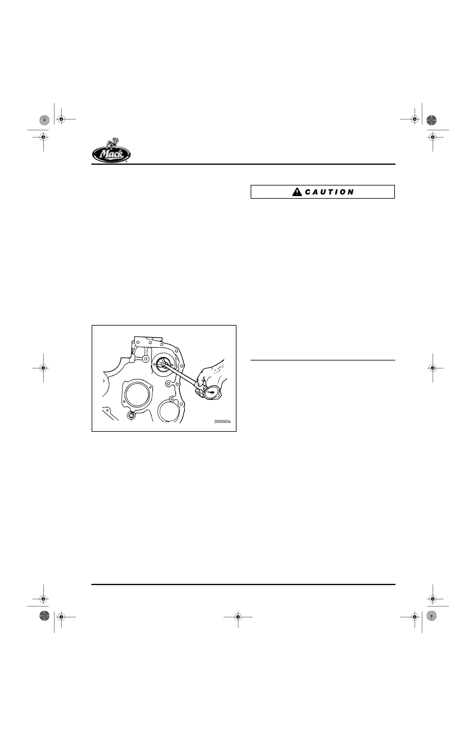
1. Using a telescoping gauge or inside
micrometer, measure the auxiliary bushing
bores. Take two readings, perpendicular to
each other, in each bore. Record the
readings. Refer to Figure 204.
2. Compare the readings with the tolerances
listed under “Fits and Limits” in the
SPECIFICATIONS section.
204
Figure 204 — Auxiliary Shaft Bushing ID Check
BUSHING REMOVAL
Use J 21428-01 to remove the bushings. If there
is any indication that a bushing has turned in the
block, check the bushing bore diameter with a
telescoping gauge or inside micrometer.
BUSHING INSTALLATION
Correct installation of the auxiliary shaft bushings
is very important. If the front bushing is
misaligned, lubrication oil flow to the front
bushing and journal will be blocked. The rear
bushing does not have any cylinder block oil
passage to align with the holes in the bushing.
However, the oil holes in the bushing and the oil
groove between those oil holes are in the most
desirable location when the bushing is installed
with indexing notches at the 5:30 and 10 o’clock
positions.
Use care not to lose the short oil feed tube,
1.25 inches (32 mm) in length, which connects
the oil feed hole in the rear of the auxiliary shaft to
the oil feed hole in the front of the air compressor
crankshaft. If it is accidentally lost during air
compressor or auxiliary shaft service work and
not reinstalled, the compressor will fail from oil
starvation. Also, the loss of oil pressure resulting
from the missing tube can cause damage and
problems in other components and parts.
Oil hole alignment of the front bushing-to-cylinder
block oil holes must be checked prior to, and at
the completion of, installation. The cylinder block
rear bushing bore has no oil holes to align with
the bushing oil holes, so simply install the
bushings with the indexing notches at the 5:30
and 10 o’clock positions. Refer to Figure 205 and
Figure 206.
5-111.bk Page 201 Monday, July 10, 2006 2:26 PM