Page 310
REPAIR INSTRUCTIONS, PART 1
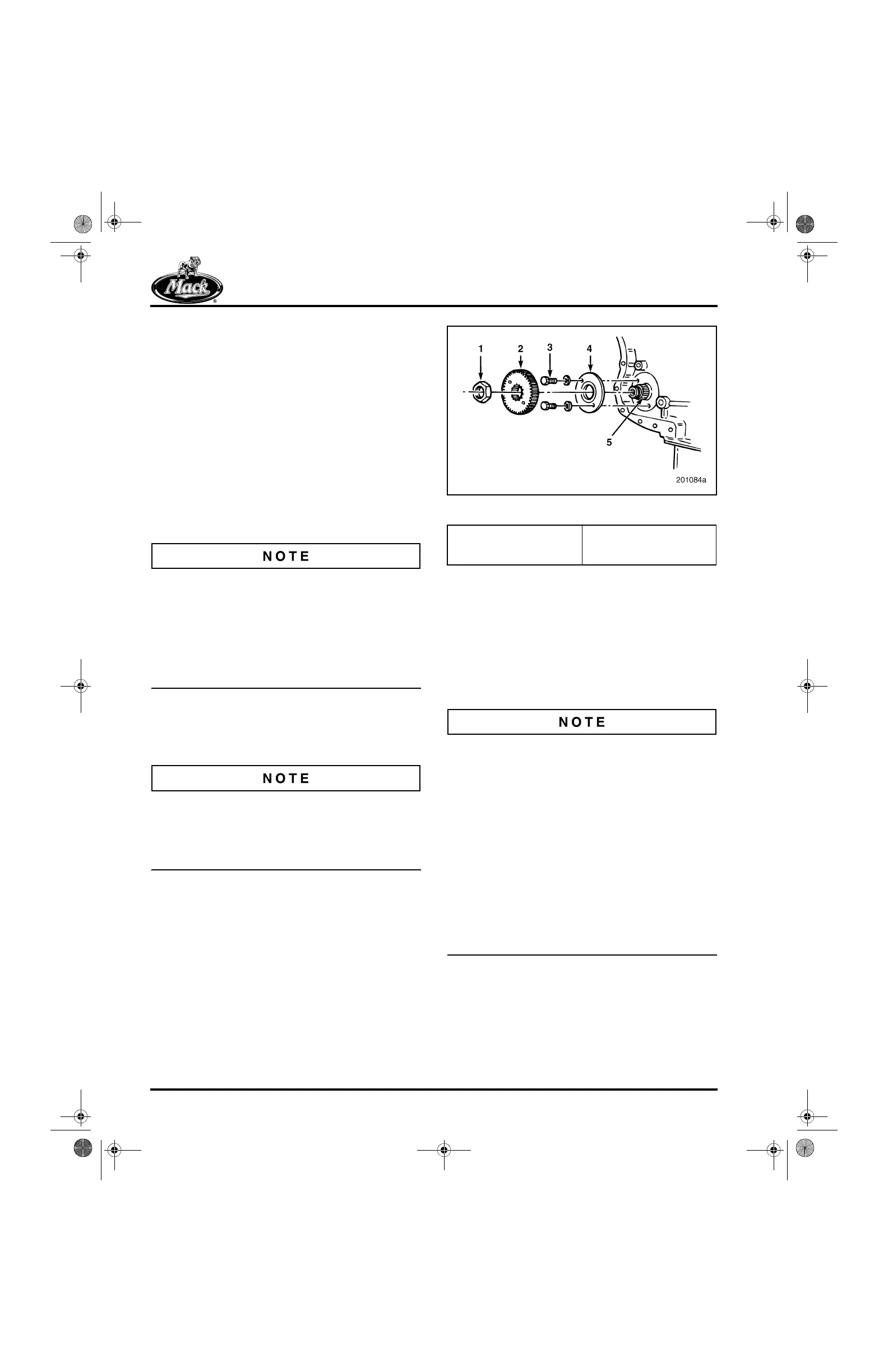
2. Install the shaft through the rear of the
auxiliary shaft housing. Use care when
aligning the shaft to avoid damage to the
rear bearing.
Refer to Figure 357.
3. Install the thrust washer and secure it in
position with the patch-lock capscrews and
hardened washers.
4. Tighten the thrust washer retaining
patch-lock capscrews to the specified
torque, 15 lb-ft (20 N폷m), using torque
wrench J 24406, or equivalent.
5. Install the auxiliary shaft gear on the shaft
splines.
The auxiliary shaft and nut threads must be clean
and dry before assembly. Clean the threads
thoroughly with Brakleen
®
or electrical contact
cleaner. If reusing the old nut, apply Loctite
®
271
or 277 to the threads and install the nut. If using a
new nut from the MACK Parts System, it is not
necessary to apply Loctite
®
as the nut threads
are coated with a pre-applied thread locker.
6. Install the auxiliary shaft nut and tighten to
the specified torque, 300 lb-ft (405 N폷m),
using torque wrench J 23775-01, or
equivalent.
Whether using a new or revised nut, it is critical
that the ground face of the nut (if applicable) be
installed toward the gear. Any identifications on
the nut face must be installed away from the
gear.
357
Figure 357 — Auxiliary Shaft Gear Installation
Oil Pump Installation
[219 MU]
Make sure that the oil pump is in satisfactory
condition as covered under “Lubrication System
Components Bench Procedures” in the REPAIR
INSTRUCTIONS section.
Because of differences in the gear set helixes of
current and earlier design engines, it is important
that the correct component/parts are installed.
앫 An improper drive gear on the oil pump will
prevent oil pump installation, assuming a
correct gear is on the auxiliary shaft.
앫 If an oil pump and an auxiliary shaft
assembly were replaced, two improper
gears could be installed, and engine failure
would result.
앫 In replacing any of these critical parts,
always refer to part number information in
the MACK Parts System to ensure the
correct component/part is being used.
1. Place the oil pump in position on the cylinder
block. Refer to Figure 358.
2. Apply Loctite
®
271 to the threads of the
pump mounting capscrews and install them.
Tighten the mounting capscrews to the
specified torque, 40 lb-ft (55 N폷m), using
torque wrench J 24407, or equivalent.
1. Nut
2. Auxiliary Shaft Gear
3. Capscrew
4. Thrust Washer
5. Shaft Splines
5-111.bk Page 310 Monday, July 10, 2006 2:26 PM