REPAIR INSTRUCTIONS, PART 1
Page 235
INSPECTION
Pressure Test — It is recommended that cylinder
heads be pressurized and checked for internal
cracks and leaks. Refer to the “Cylinder Head
and Cylinder Block Leak Test” procedure in the
TROUBLESHOOTING section.
Check the cylinder head deck surface for
warping, pitting or other imperfections. Deck
surface flatness must not vary more than
0.0015 inch (0.0381 mm) over 18 inches
(45.7 cm) of surface area. Resurface or replace
as necessary.
When resurfacing, remove a minimum amount of
material from the deck to obtain a flat, uniform
surface. Standard head height is
6.397–6.391 inches (162.483–162.310 mm). A
maximum of 0.010 inch (0.254 mm) of material
may be removed, making the minimum height of
a resurfaced head 6.381 inches (162.077 mm).
When the deck is resurfaced, the fire ring groove
and valve seat insert dimensions must be
reestablished following the procedure under “Fire
Ring Groove Cutting.”
Fire Ring Groove Cutting
GENERAL INFORMATION
Fire ring grooves are located in the machined flat
surface (deck) of the cylinder head that mates
with the engine block. This design provides a
locking groove for the fire ring to seat, as well as
a positive-combustion pressure seal.
After resurfacing the cylinder head deck, it is
necessary to reestablish the fire ring groove
depth using the fire ring groove cutter J 29600-C
(Figure 249).
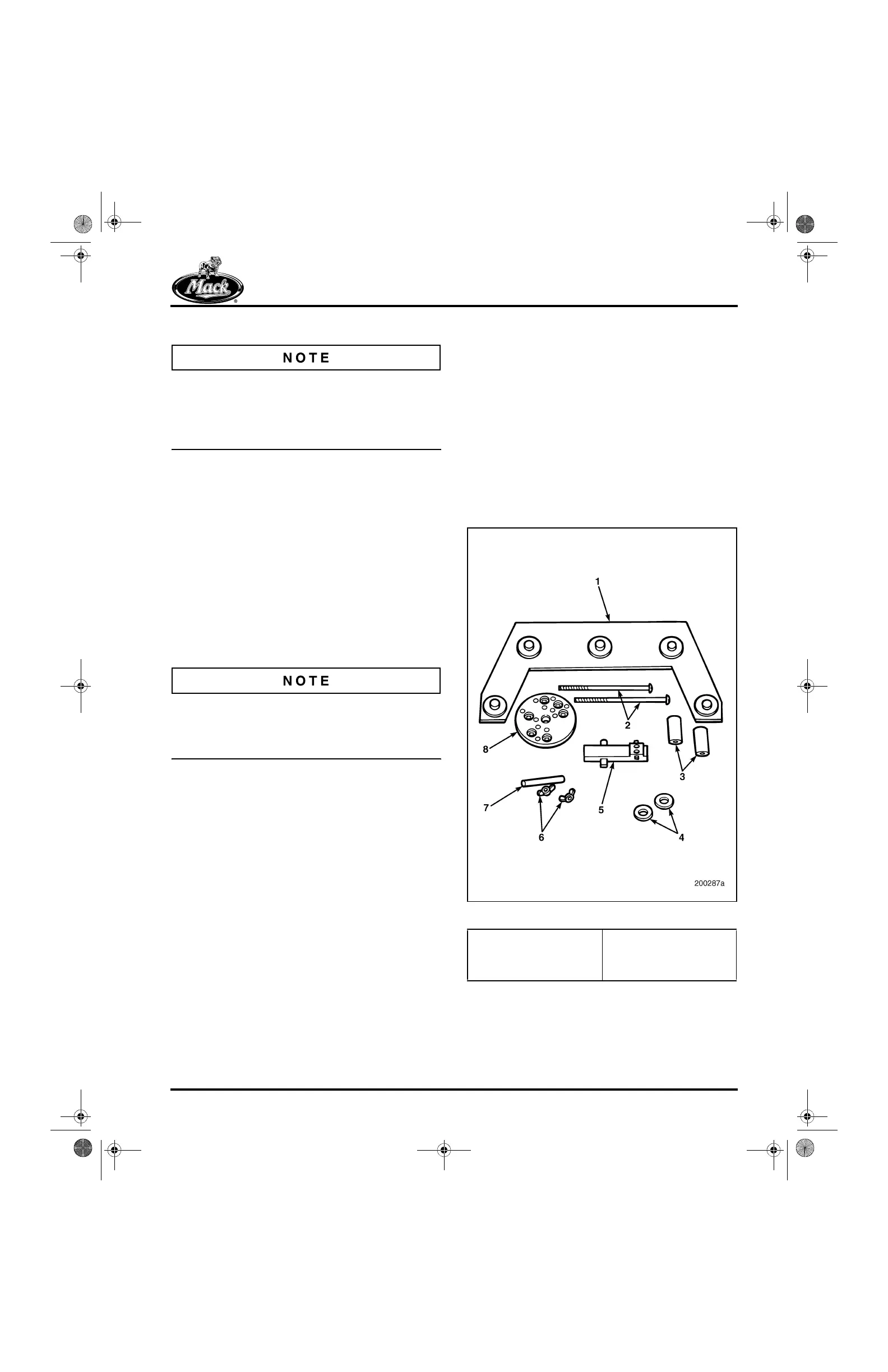
249
Figure 249 — Fire Ring Groove Cutter J 29600-C
1. Alignment Fixture
2. Hold-Down Capscrews
3. Spacers
4. Washers
5. Cutter Head (J 37719)
6. Wing Nuts
7. Thickness Gauges
8. Cutter Base
5-111.bk Page 235 Monday, July 10, 2006 2:26 PM