Page 402
REPAIR INSTRUCTIONS, PART 2
EGR SYSTEM SERVICE
PROCEDURES (IN-CHASSIS)
FOR ASET™ AC ENGINE
Preliminary Steps
The preliminary steps for replacing the EGR
system components will vary depending on the
chassis configuration. As such, the steps in the
procedures that follow are general in nature.
Begin the operations by disconnecting the battery
and draining fluids from the engine as required
(draining fluids is only required to remove the
EGR cooler assembly). Then, remove ducting
and any accessory items, etc., that may interfere
with access to the EGR components.
EGR Gas Tube(s) Removal and
Installation
Early-production engines are equipped with a
two-piece cool tube assembly. The two-piece
cool tube, however, has been replaced with a
one-piece assembly effective with December
2003 production. The one-piece assembly uses
coupling hoses for the connections at the mixer
tube and EGR cooler. If the mixer tube and EGR
cooler have flange-style port connections,
coupling adapters are used in combination with
the coupling hoses.
COOL TUBE REMOVAL (ONE-PIECE
ASSEMBLY)
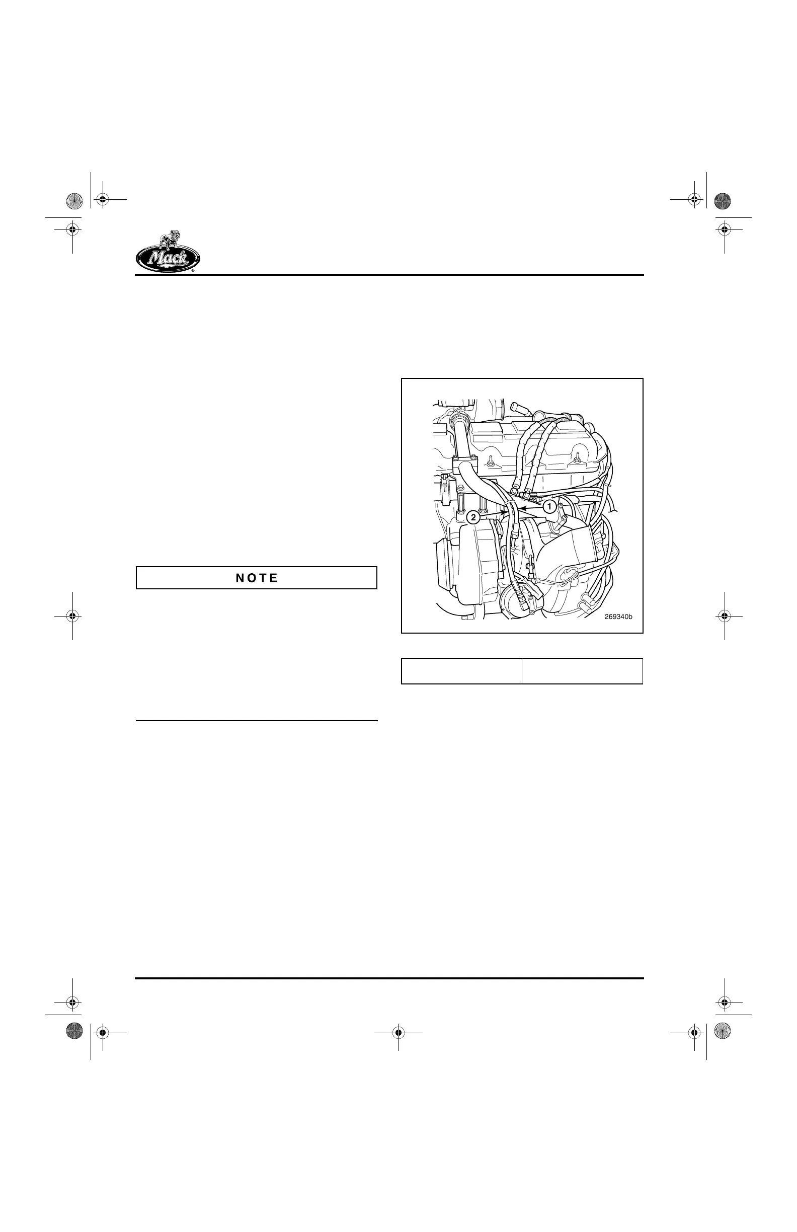
1. Disconnect the turbocharger oil supply line
and the air line to the VTG actuator at the
turbocharger (Figure 483). Plug the fittings
to keep dirt and debris out.
483
Figure 483 — Oil Supply and Air Lines
2. Loosen and remove the clamps securing the
cool tube to the brackets at the EGR valve
and the front section of the exhaust manifold
(Figure 484).
1. Turbocharger Oil Supply
Line
2. VTG Actuator Air Line
5-111.bk Page 402 Monday, July 10, 2006 2:26 PM