REPAIR INSTRUCTIONS, PART 1
Page 219
AUXILIARY SHAFT AND
CAMSHAFT BENCH
PROCEDURES
Auxiliary Shaft Inspection
[212 CV]
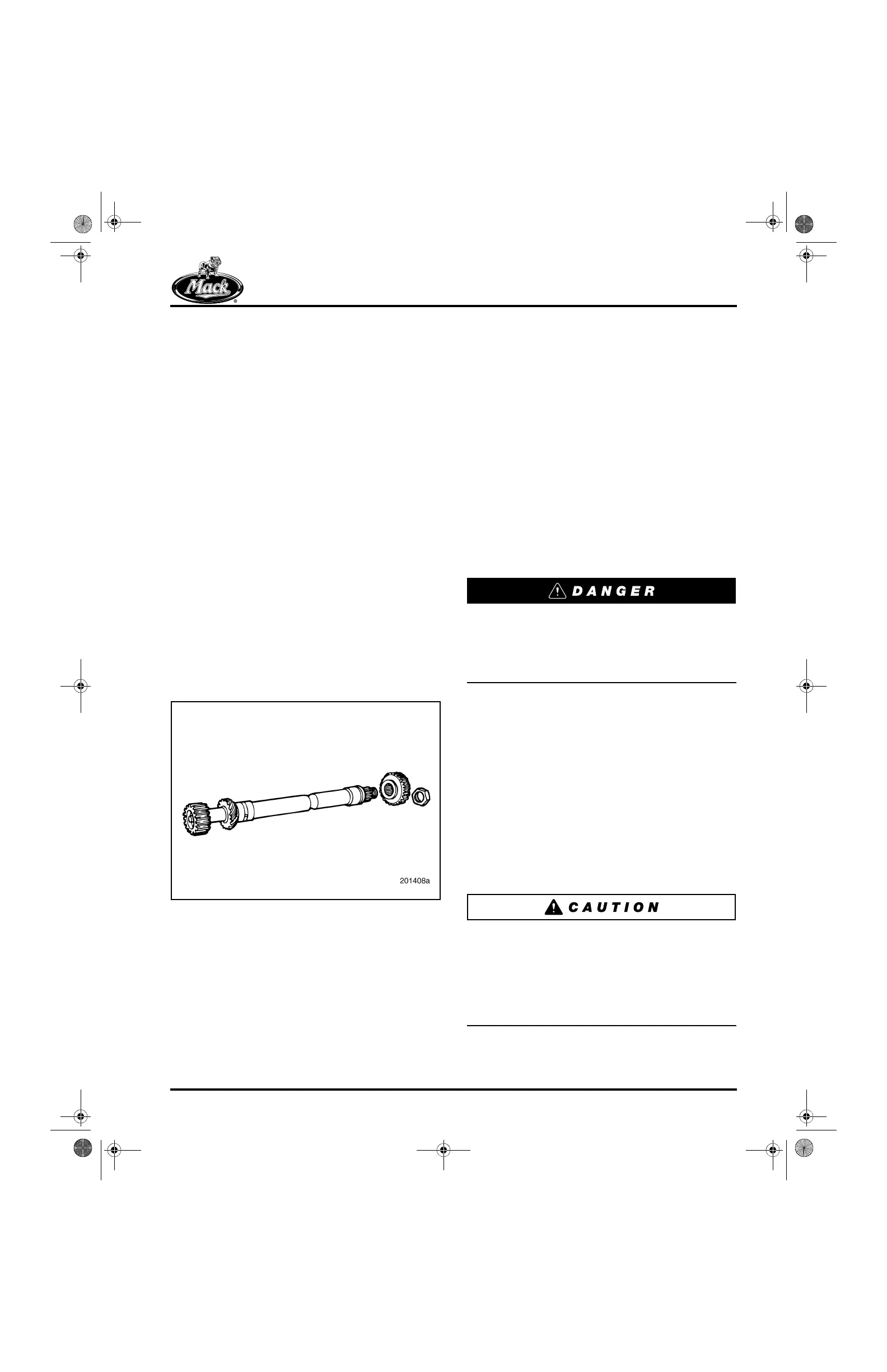
The auxiliary shaft is identified by three machined
circumferential cuts in front of the stamped part
number.
INSPECTION
Refer to Figure 226.
1. Thoroughly clean the auxiliary shaft.
2. Inspect the shaft journals and splines, and
gear teeth and splines for evidence of
cracks, pitting, scoring or severe wear. If any
of these conditions exist, replace the
auxiliary shaft.
3. Make sure the orificed cup plug is in place in
the internal passage at the front of the
auxiliary shaft.
226
Figure 226 — Auxiliary Shaft
Camshaft Inspection
[213 CH]
GENERAL INSTRUCTIONS
All ASET™ engine models use a straight key,
P/N 43AX9, in the camshaft-to-gear keyway. The
offset key used in earlier MACK engine models
no longer applies.
CAMSHAFT GEAR REMOVAL
An extremely tight interference fit holds the cam
gear on the camshaft. Typically, 10 tons of force
is required to remove the gear. When cam gear
removal or installation is required, use the
following procedures.
A considerable amount of force may be
necessary to remove damaged or spun gears.
DO NOT apply more than 25 tons (22.7 metric
tons) of force to gears. Doing so may shatter
the gears and result in severe personal injury.
Refer to Figure 227.
1. Position two adequate steel plates on the
press to support the camshaft gear. The
plates should have a 4-inch (101.6 mm) hole
cut out in the center when placed
side-by-side, or similar size V-grooves, to
allow clearance for the shaft journals while
providing optimum support for the gear.
2. Set the camshaft, supported by the gear,
into the press.
3. Using a suitable arbor, press the camshaft
out of the gear.
Make sure there is enough clearance between
the end of the camshaft and the floor while
removing the gear. Do not let the camshaft fall or
strike the floor when pressed through the gear.
The camshaft can be bent easily, and may go
unnoticed. Installing a bent camshaft in the
engine could result in cam bushing failure.
4. Remove the thrust washer.
5-111.bk Page 219 Monday, July 10, 2006 2:26 PM