REPAIR INSTRUCTIONS, PART 1
Page 251
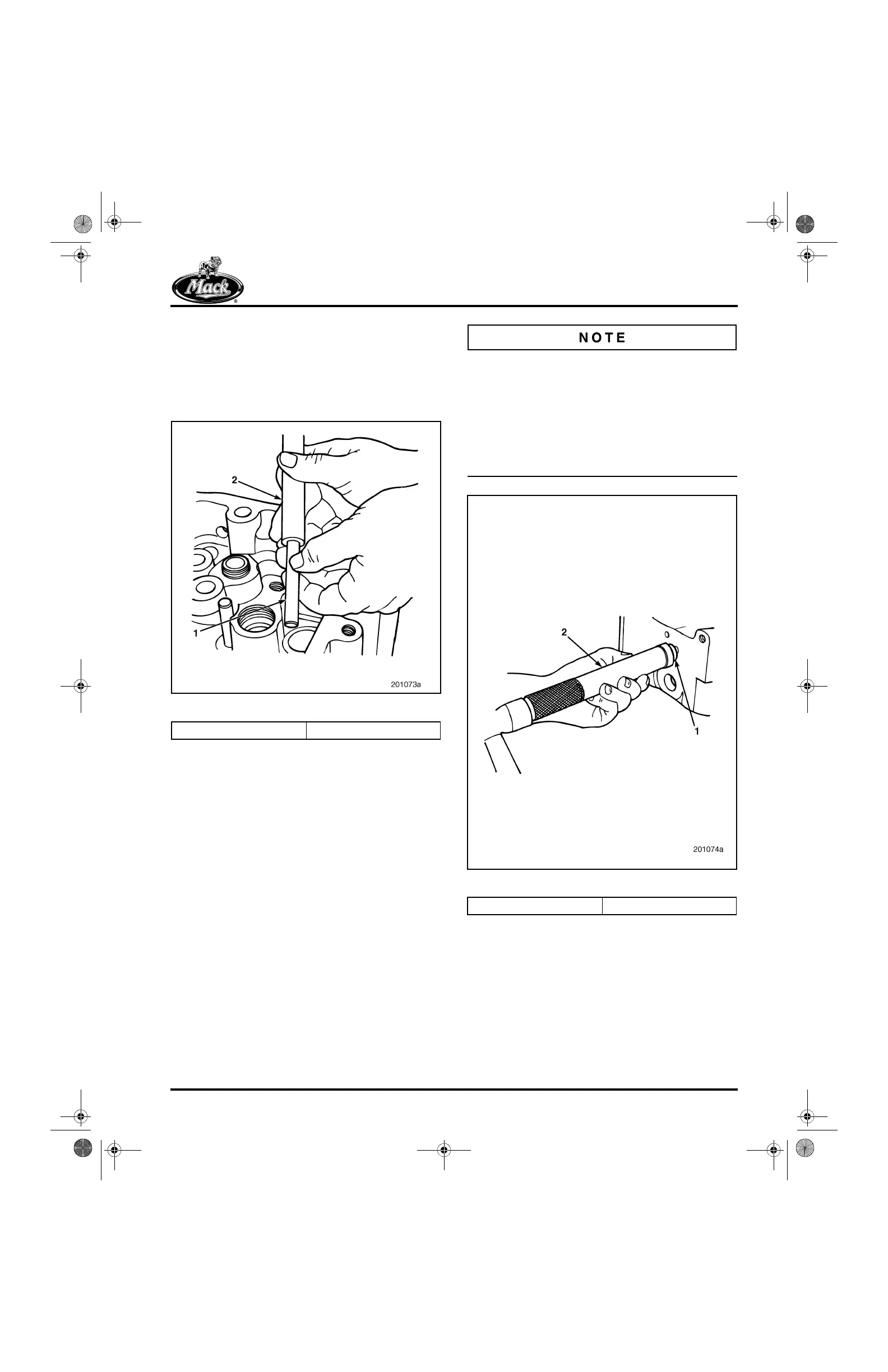
INSTALLATION PROCEDURE
Place the new valve yoke guide pin in position
and use guide pin installer J 29296 to drive the
pin into the cylinder head. The guide pin will be at
the correct height when the tool bottoms on the
cylinder head. Refer to Figure 274.
274
Figure 274 — Valve Yoke Guide Pin Installation
Cylinder Head Cup Plug
Replacement
[213 FP]
The cylinder head has two different size cup
plugs. Both sizes are installed using the following
procedure:
1. Clean the cup bore thoroughly.
2. Using Loctite
®
277 sealer, or equivalent,
apply the sealer to the cup plug and plug
bore in the head.
3. Install the cup plugs in the cylinder head,
using the appropriate cylinder head core
plug installer, J 34684 for 13/16-inch
(20.64 mm) cup plugs, and J 34687 for
1-1/16-inch (26.99 mm) cup plugs. Refer to
Figure 275.
앫 The cup plug should be driven in until the
outer lip of the plug is 0.030 inch (0.762 mm)
below the bottom of the lead-in chamfer. An
additional driver may be required to achieve
this cup plug depth.
앫 The outer lip of the plug must always locate
in the hole and not overlap the lead-in
chamfer.
275
Figure 275 — Cylinder Head Cup Plug Installation
1. Valve Yoke Guide Pin 2. J 29296
1. Cup Plug 2. Cup Plug Installer
5-111.bk Page 251 Monday, July 10, 2006 2:26 PM