Page 344
REPAIR INSTRUCTIONS, PART 1
Air Inlet Manifold Installation
[214 HD]
Refer to Figure 404.
1. Lubricate the threads of the air inlet manifold
capscrews.
2. Place the inlet manifold in position on the
cylinder head and install the capscrews.
3. Torque the capscrews to 40 lb-ft (54 N폷m),
using torque wrench J 24407, or equivalent.
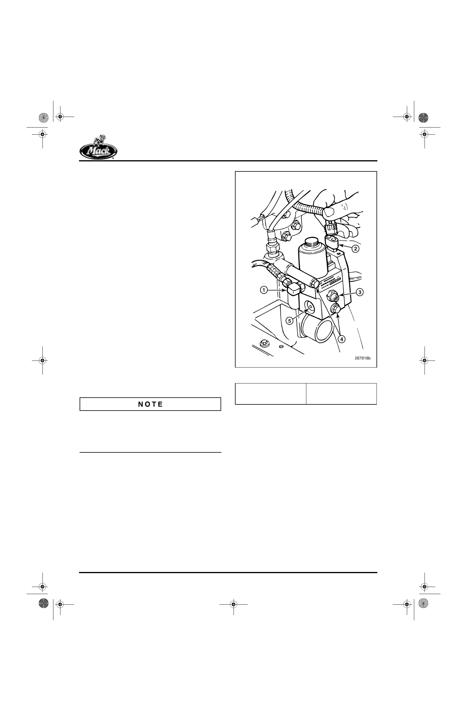
VTG Position Control Valve
Installation
[214 QB]
Refer to Figure 405 as reference for installing the
VTG position control valve.
1. Place the control valve assembly in position
on the inlet manifold and install the two
mounting capscrews. Tighten the capscrews
to specification.
2. Connect the actuator air line to the fitting at
the side of the valve.
3. Connect the harness electrical lead to the
terminal at the top of the valve.
If the engine is equipped with a coalescing air
filter, the air line between the VTG position
control valve and the filter IS NOT installed until
after the engine is removed from the engine
stand.
405
Figure 405 — VTG Position Control Valve
1. Air Line to VTG Actuator
2. Electrical Connector
3. Air Supply Port
4. Mounting Capscrews
5. Air Bleed Port
5-111.bk Page 344 Monday, July 10, 2006 2:26 PM