REPAIR INSTRUCTIONS, PART 1
Page 343
403
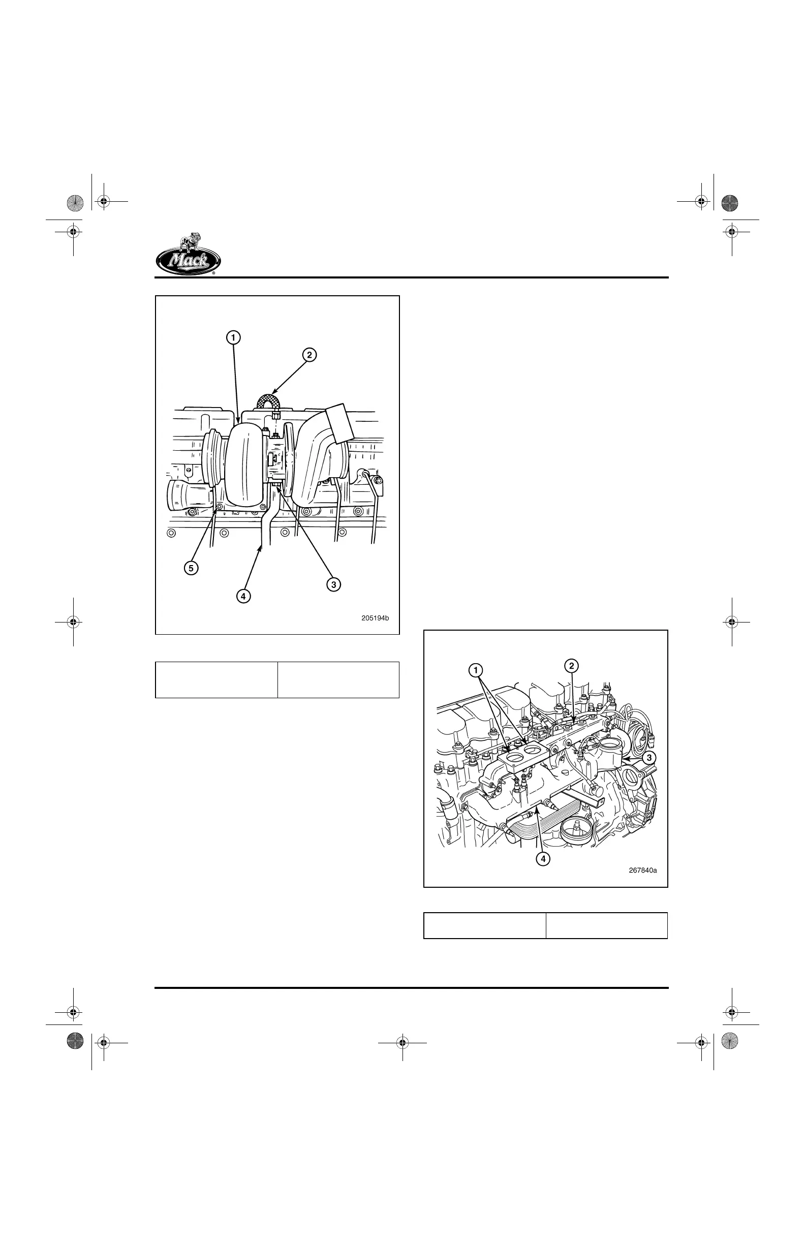
Figure 403 — Turbocharger Installation
Coolant Manifold Installation
[215 NK]
INSPECTION
Check the coolant manifold for restrictions,
cracks and flange wear. The manifold cannot be
repaired. Replace if any signs of damage are
present.
INSTALLATION PROCEDURE
Refer to Figure 404
1. Ensure that the manifold is clean. Place a
new coolant/air inlet manifold gasket in
position on the mounting surface of each
cylinder head.
2. Lubricate the threads of the coolant manifold
flangehead capscrews with clean engine oil.
3. Place the manifold in position on the cylinder
heads and insert the capscrews. Tighten the
capscrews to the specified torque, 40 lb-ft
(55 N폷m), using torque wrench J 24406, or
equivalent.
404
Figure 404 — Coolant and Air Inlet Manifolds
1. Turbocharger
2. Lubrication Supply Hose
3. Capscrew
4. Lubrication Drain Tube
5. Mounting Nut
1. Thermostat Ports
2. Coolant Manifold
3. Mixer Tube Mounting
4. Inlet Manifold
5-111.bk Page 343 Monday, July 10, 2006 2:26 PM