Page 336
REPAIR INSTRUCTIONS, PART 1
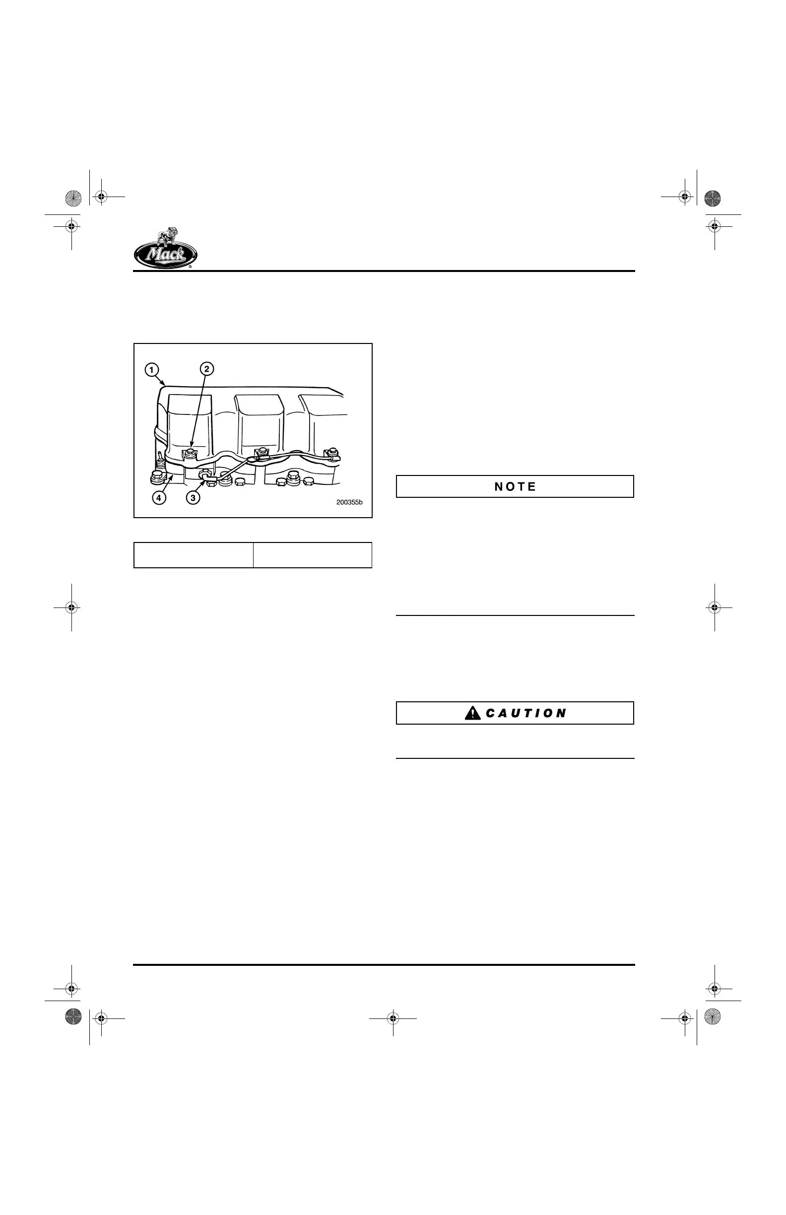
6. Place the cylinder head covers in position on
the cylinder heads or on the J-Tech™
spacers (if so equipped) as shown in
Figure 394.
394
Figure 394 — Cylinder Head Cover Installation
7. Place the isolators in position on top of the
cylinder head cover′s bolt holes.
8. Lubricate the threads of the capscrews and
install the capscrews in the cylinder head
covers. Tighten the capscrews to the
specified torque, 16 lb-ft (22 N폷m).
Oil Fill Tube/Dipstick Installation
ASET™ AC ENGINE
The oil fill and dipstick tubes are located on the
left side of the engine. As such, it cannot be
reinstalled until the engine has been removed
from the engine stand.
Air Compressor Installation
[261 CK]
Refer to Figure 395.
If the compressor drive coupling has been
removed or a replacement compressor is being
installed, air compressor coupling holder tool
J 41071 will be required to hold the compressor
shaft while the coupling nut is being torqued.
Torque the coupling nut to 60 lb-ft (81 N폷m). Do
not use air impact wrench (air gun), use an
accurately calibrated torque wrench such as
J 24406, or equivalent.
1. Install a new gasket on the air compressor
mounting flange.
2. Check to ensure that the lubrication oil
supply tube is in place and position the air
compressor on the mounting flange.
If the oil supply tube is lost, the air compressor
will fail from lack of oil.
3. Install the three mounting capscrews and
tighten to the specified torque, 80 lb-ft
(108 N폷m), using torque wrench J 24407, or
equivalent.
4. Reconnect the coolant lines to the air
compressor cylinder head.
1. Cylinder Head Cover
2. Capscrew
3. Actuator
4. Spacer
5-111.bk Page 336 Monday, July 10, 2006 2:26 PM