REPAIR INSTRUCTIONS, PART 1
Page 335
391
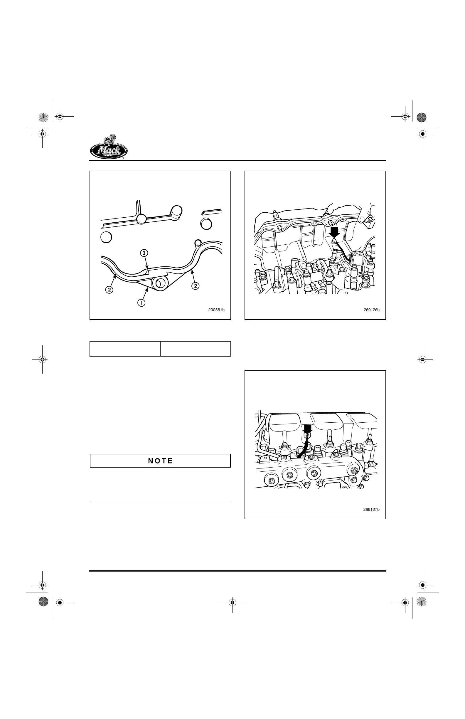
Figure 391 — Gasket Installation (Offset Joined Section
Shown)
2. Place the spacers (if equipped) in position
on the cylinder heads.
3. For the engines equipped with J-Tech™
engine brake, connect the electrical lead
between the spacer and the actuator on the
brake housing.
4. On the MACK PowerLeash™ engine brake,
connect the electrical lead from the rocker
arm solenoid to the cylinder head cover
electrical pass-through connector, inside the
cover.
At installation of the cylinder head covers, do not
place any pull-stress on the solenoid wire.
Overstressing the wire could result in engine
brake malfunction.
392
Figure 392 — Cylinder Head Cover Inner Connection
5. For the PowerLeash™, connect the
electrical lead from the engine harness to
the electrical pass-through connector on the
outside of the cylinder head cover.
393
Figure 393 — Cylinder Head Cover Electrical Connection
1. Cylinder Head Cover
2. Seal Strip
3. Seal Groove
5-111.bk Page 335 Monday, July 10, 2006 2:26 PM