Page 320
REPAIR INSTRUCTIONS, PART 1
MANIFOLD INSTALLATION
1. Install the 12 new studs from the MACK
Parts System in position on the cylinder
head. Studs must be installed dry (no
lubrication). Tighten the studs to the
specified torque while maintaining
mandatory stud protrusion of 1.75 inches
(44.45 mm).
2. Place six new manifold gaskets in position
on the studs.
3. Place the exhaust manifold in position on the
mounting studs. Oil the nut threads and
flanges with clean engine oil and install the
12 retaining nuts.
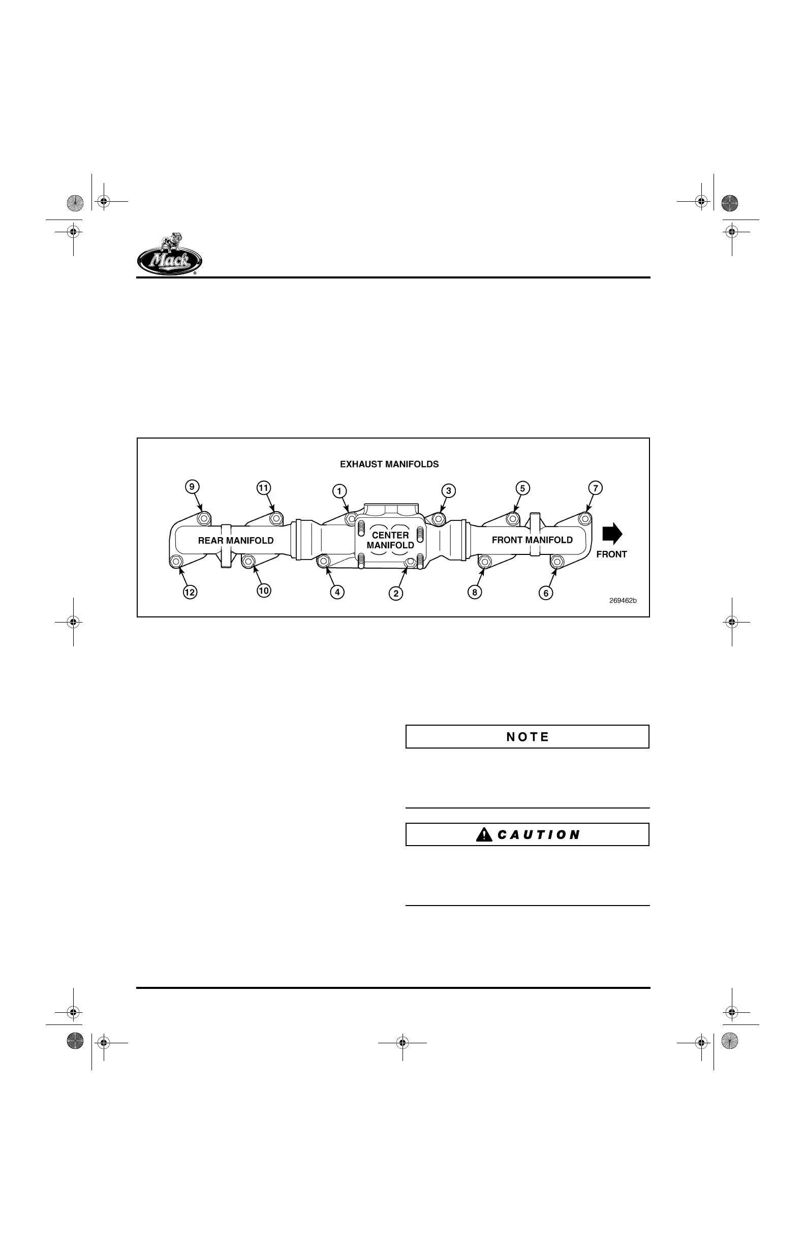
4. Tighten the nuts in two stages following the
sequence shown in Figure 370:
앫 First stage — 50 lb-ft (68 N폷m)
앫 Second stage — 100 lb-ft (136 N폷m)
370
Figure 370 — Exhaust Manifold Tightening Sequence
Nozzle Holder Assembly Installation
[222 KG]
GENERAL INFORMATION
The nozzle holder is positioned vertically in the
cylinder head and centered in the cylinder
between the four valves. The nozzle fuel inlet
tube is inserted through the side of the cylinder
head with the tapered end of the inlet tube
sealing the area between the tube and the nozzle
holder. The tube is secured in position with a
sleeve nut.
SPECIAL TOOL REQUIRED
앫 Injection Nozzle Puller J 37093
INSTALLATION PROCEDURE
1. Install the washer-type gasket in place on
the bottom of the nozzle, using a small dab
of grease to hold it in place (recommended
method).
An alternate method is to drop the washer-type
gasket into the nozzle holder sleeve bore as
shown in Figure 371. Make sure that the gasket is
centered and lying flat in the bottom of the bore.
Care must be taken with either method of
installation to NOT misposition the gasket. If
mispositioned, the washer may be damaged and
result in severe combustion leakage.
5-111.bk Page 320 Monday, July 10, 2006 2:26 PM