REPAIR INSTRUCTIONS, PART 1
Page 339
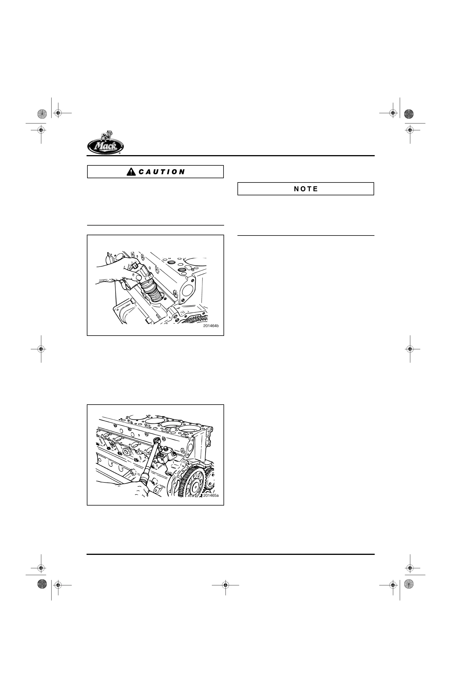
To avoid O-ring damage, the cam lobe must be
positioned with the base circle up prior to
installation of each EUP. Engine barring tool (tool
No. J 3857-A) MUST be used to rotate the
engine. DO NOT use the starter to rotate the
engine.
397
Figure 397 — Unit Pump Installation
3. Install new mounting screws. Lubricate the
threads and underside of each screw with
clean engine oil prior to installation. Tighten
the screws evenly to draw the EUP into the
cylinder block (Figure 398). Final tighten the
screws to the specified torque, 60 lb-ft
(81 N폷m).
398
Figure 398 — Tightening Unit Pump Fasteners
4. Repeat steps 2 and 3 to install the five
remaining EUP assemblies.
If an EUP has been replaced with a new unit, the
new unit must be calibrated as described under
“Engine Setup and Adjustments” in the REPAIR
INSTRUCTIONS section. Calibration of the unit
pumps ensures optimum engine performance.
Engine Wiring Harness Installation
1. Place the wiring harness in position on the
engine and secure it with the attaching
hardware.
2. Connect the harness at each of the EUP
terminals.
3. Connect the harness at the EECU. Make
sure the locking tabs are in place.
4. Connect the harness to any sensors or other
components now installed or as reassembly
progresses.
Fuel Nozzle Inlet Tube Assembly
Installation
[222 KD]
The fuel nozzle inlet tube assemblies are
identical for all six cylinders and are installed in
the same way. Refer to Figure 400.
1. Place the EGR heat shield in position over
the front section of the exhaust manifold
(Figure 401). Install the top capscrew
attaching the shield to the cylinder block and
tighten it to specification. DO NOT install the
bottom capscrews at this time.
2. Inspect the high-pressure fuel lines before
installation. If the collars of any of the
high-pressure lines are “mushroomed” or
exhibit other types of damage, replace with a
new fuel line. An example of a mushroomed
collar is shown in Figure 399.
5-111.bk Page 339 Monday, July 10, 2006 2:26 PM