Page 170
REPAIR INSTRUCTIONS, PART 1
Should the cylinder head cover be removed
without first disconnecting the solenoid wire from
the connector on the inside of the cover, the wire
can easily be damaged. Failure of the engine
brake to operate (on one or both cylinder heads),
or intermittent operation following removal and
reinstallation of the cylinder head cover(s) is most
likely caused by a damaged engine brake
solenoid lead. In most cases, fault code 3-5 or
3-6 will be logged.
WITH J-TECH™ ENGINE BRAKE
1. Remove the cylinder head covers by
removing the six retaining capscrews and
isolators from each cover. Remove the
cover and discard the cover seals.
2. Remove the control wire from the left side of
each cylinder head cover or spacer housing.
3. Disconnect the wires at the actuator
solenoid connector.
4. Remove the spacer housings and spacer
seals.
164
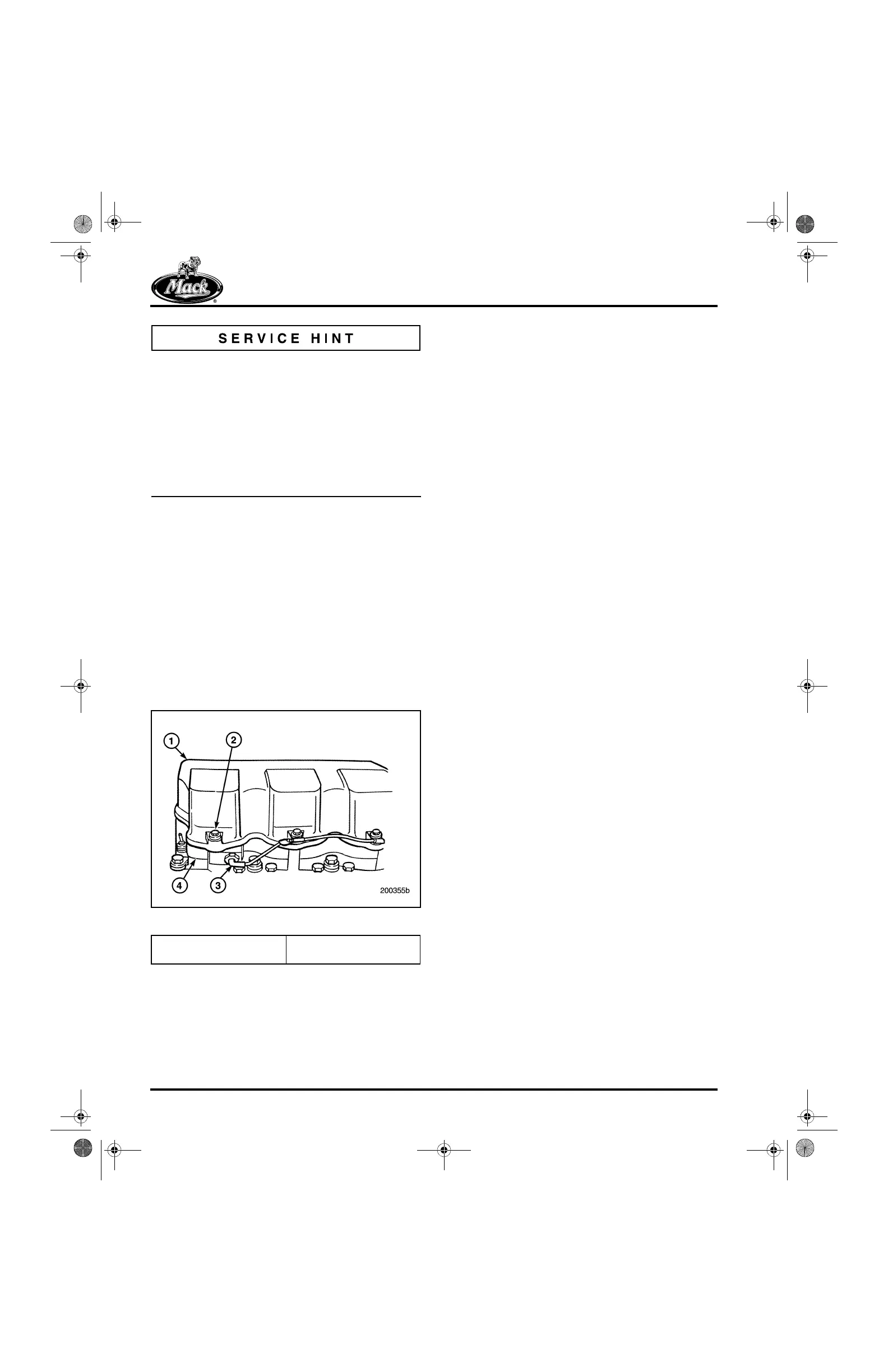
Figure 164 — J-Tech™ Cylinder Head Cover and Spacer
Rocker Arm, Valve Yoke and Push
Rod Removal
[213 LP, NV & LH]
ENGINES WITH J-TECH™ ENGINE BRAKE
Refer to Figure 165.
1. If the engine is equipped with a J-Tech™
engine brake, remove the six capscrews and
washers retaining the brake actuator
assembly and rocker arm assembly to each
cylinder head.
2. Remove and mark the J-Tech™ control
wire.
3. Remove the brake actuator and rocker arm
assemblies from each cylinder head (one
actuator and rocker arm assembly per
head).
4. Remove the valve yokes from each pair of
valves by lifting straight up on each yoke.
Tag the yokes for reassembly in the same
location.
5. Remove the valve push rods and tag the
rods for reassembly.
1. Cylinder Head Cover
2. Capscrew
3. Control Wire
4. Spacer Housing
5-111.bk Page 170 Monday, July 10, 2006 2:26 PM