Page 366
REPAIR INSTRUCTIONS, PART 1
Dipstick Tube Installation
All AC engines have the dipstick tube installed in
the oil pan on the left side of the engine.
Installation instructions are as follows:
1. Install the tube guide into the side of the oil
pan and tighten the guide nut to
specifications.
2. Apply Loctite
®
242 (blue) to the threads of
the dipstick tube attaching capscrew.
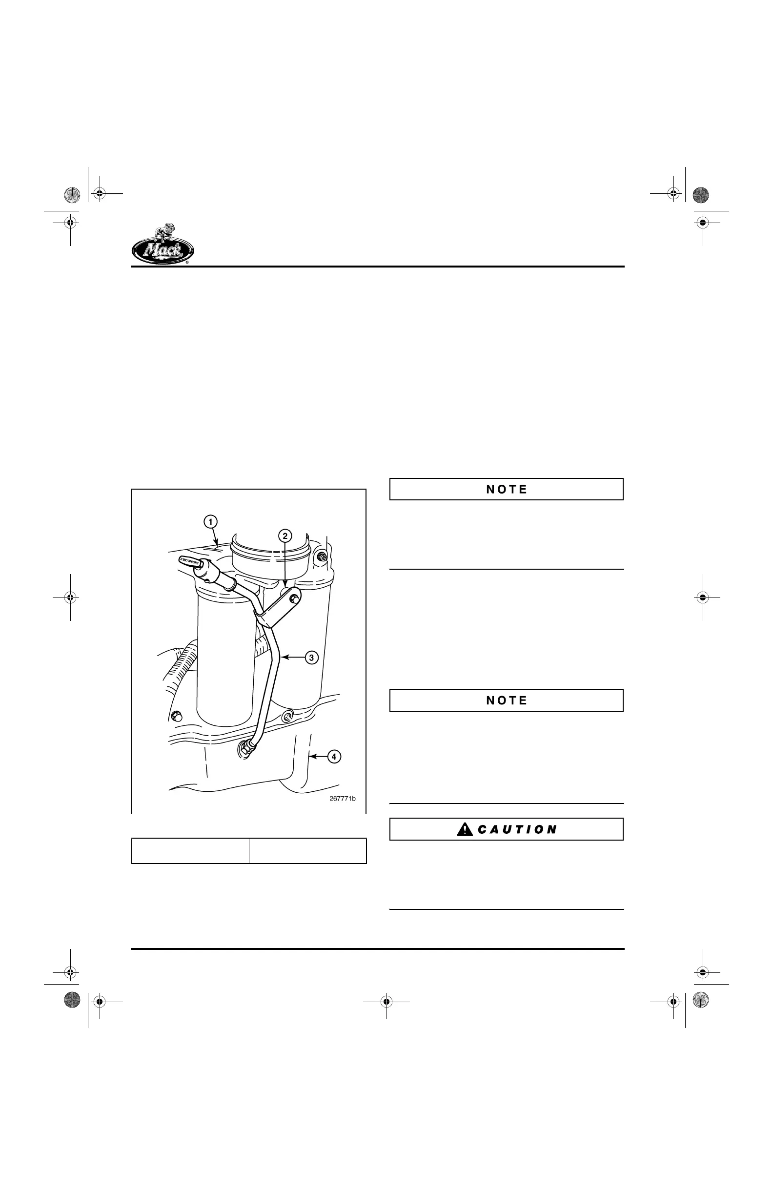
3. Insert the dipstick tube into the guide tube
and attach the tube to the oil filter pedestal
bracket with the capscrew. Locate the
isolator between the tube bracket and oil
filter pedestal, as shown in Figure 443.
443
Figure 443 — Dipstick, Left-Side Installation
4. Tighten the dipstick tube attaching capscrew
to the specified torque of 24 lb-in (3 N폷m).
5. Install the dipstick guide tube compression
nut and tighten to specifications.
ENGINE INSTALLATION
General Instructions
Engine installation details vary from vehicle to
vehicle. The following procedure provides
general installation guidelines for MACK engines.
Before beginning, make sure all equipment has
been inspected for safety and is available for use.
Place the vehicle on a flat, level surface. Make
sure the area has ample work space.
Engine Installation into Vehicle
Obtain assistance when installing the engine. Be
sure to watch for obstructions, such as engine or
chassis components, brackets, clamps or other
components, that may interfere with installation of
the engine.
1. Using a suitable lifting device, lower the
engine into position on the chassis.
2. Align the engine with the torque converter or
clutch (as applicable) and install the
transmission bell housing-to-flywheel
housing capscrews. Tighten the capscrews
to specification which is dependent on size
of fastener.
A new-style flywheel housing initiated into
production in mid-2004, introduced a larger
transmission-to-flywheel housing connection bolt.
The bolt size increases from 10 mm to 7/16-inch.
This bolt size change will need to be considered if
the flywheel housing was replaced during
overhaul.
If the flywheel housing was replaced with the
new-style which uses a 7/16-inch
transmission-to-flywheel housing bolt, it is very
important to also use the correct hardened
washer with this bolt.
1. Filter Mounting Bracket
2. Isolator
3. Dipstick Tube
4. Oil Pan
5-111.bk Page 366 Monday, July 10, 2006 2:26 PM