REPAIR INSTRUCTIONS, PART 1
Page 365
5. Install the filter assembly pedestal onto the
stud with the forward end of the assembly
tilted downward approximately 1 inch (to
allow clearance with the inlet manifold).
Once the assembly is mounted on the stud,
pivot the assembly clockwise to align the
remaining three mounting holes of the
pedestal, making sure the gasket remains in
the proper position.
6. With the mounting holes of the pedestal
aligned, install the bolt in the upper front
mounting hole position. Then, install the
remaining two bolts in the lower mounting
holes.
7. Remove the stud from the upper right
mounting hole, then install the mounting
bolt.
8. Snug all bolts in a criss-cross pattern, then
tighten to 40 lb-ft (55 N폷m).
9. Slide the cooler-to-water pipe hose from its
previously positioned location on the pipe to
be centered between the cooler and the
water pipe.
10. Properly position the two hose clamps and
tighten in position.
11. Install the Y-hose and clamps at the bottom
of the by-pass tube and the oil cooler inlet.
Tighten the clamps to specification.
12. Install the turbocharger lubrication supply
line.
13. Connect the harness to the oil pressure and
oil temperature sensors on the filter
mounting bracket.
442
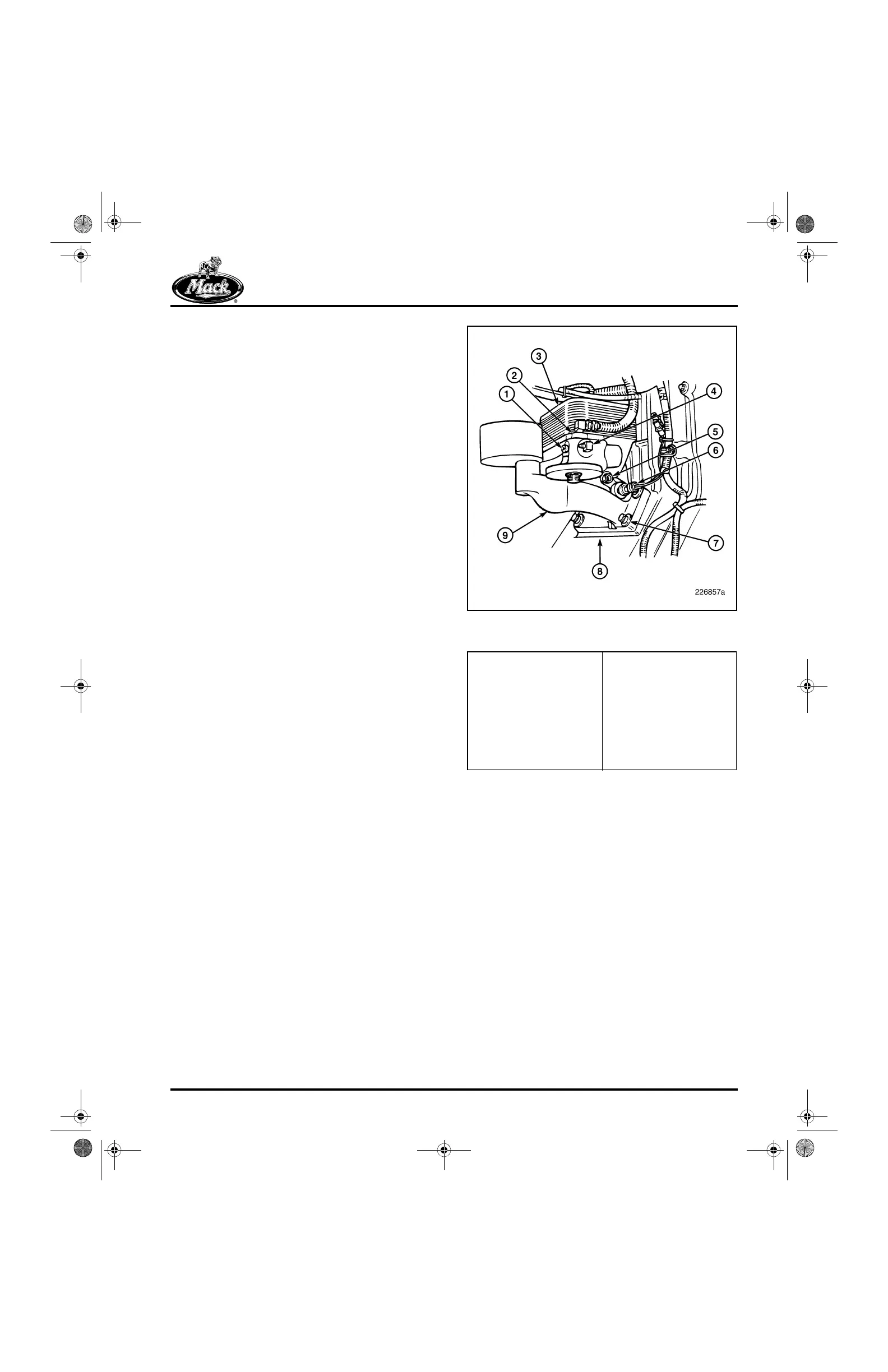
Figure 442 — Plate-Type Oil Cooler and Oil Filter
Mounting Bracket Installation
1. Oil Supply Port for
Mechanical Oil Pressure
Dashboard Gauge
2. Turbocharger Lubrication
Supply Port
3. Oil Cooler
4. Oil Supply Port for
REPTO, Turbo Unloader
and Remote-Mounted Oil
Filter
5. Oil Temperature Sensor
Port
6. Oil Pressure Sensor
7. Mounting Capscrews
8. Cylinder Block
9. Oil Filter Mounting
Bracket
5-111.bk Page 365 Monday, July 10, 2006 2:26 PM