REPAIR INSTRUCTIONS, PART 2
Page 417
INSTALLATION PROCEDURE
Refer to Figure 506.
1. Place the EGR valve heat shield in position
over the front section of the exhaust
manifold.
2. Lubricate the fuel nozzle inlet tube clamping
screw threads for each assembly before
installing.
3. Install the No. 1 fuel nozzle inlet tube
assembly into the cylinder head until light
contact is made with the nozzle holder.
Lightly tighten the clamping screw.
4. Connect the line at the No. 1 unit pump.
Tighten the clamping screw to the specified
torque using torque wrench J 24407, or
equivalent.
앫 Line clamping screw at cylinder head:
35 lb-ft (47 N폷m)
앫 Line nut at EUP: 25 lb-ft (34 N폷m)
5. Repeat steps 3 and 4 to install the fuel
nozzle inlet tube assembly at the No. 2
cylinder.
6. Place the inner EUP heat shield in position
against the cylinder block. The bottom
flange of the lower EGR heat shield fits
between the EUP heat shield and the block.
7. Install the four capscrews to secure the inner
EUP heat shield. Tighten the capscrews to
specification, 15 lb-ft (20 N폷m).
8. Install the outer EUP heat shields and
retaining nuts. Tighten the nuts to
specification, 15 lb-ft (20 N폷m).
EGR Gas Mixer Tube Removal and
Installation
REMOVAL PROCEDURE
1. Disconnect the electrical leads to the
CMCAC outlet pressure and temperature
sensors.
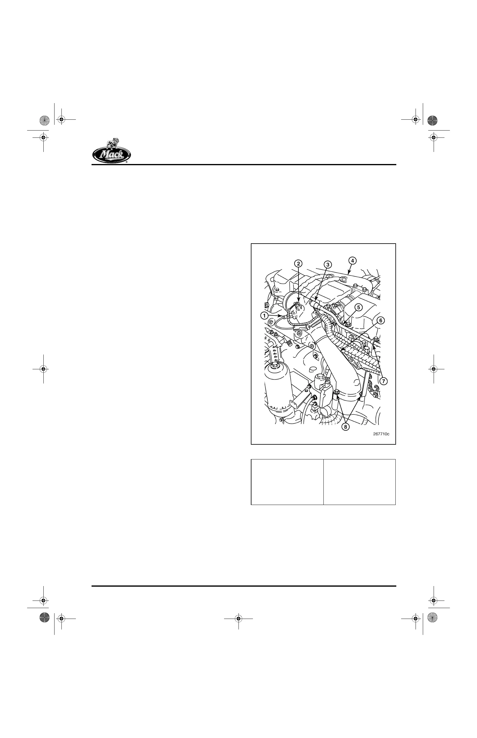
507
Figure 507 — EGR Gas Mixer Tube
2. Loosen the two band clamps securing the
flexible tapered boost pressure relief valve
(turbo by-pass) coupling hose. Remove the
two clamps and coupling hose.
1. CMCAC Pressure
Sensor
2. CMCAC Temperature
Sensor
3. Boost Pressure Relief
Valve (Turbo By-Pass)
4. EGR Cool Tube
5. Boost Pressure Relief
Outlet Tube
6. Mixer Tube
7. Boost Pressure Relief
Outlet Tube Clamp
8. Capscrews
5-111.bk Page 417 Monday, July 10, 2006 2:26 PM