Page 418
REPAIR INSTRUCTIONS, PART 2
508
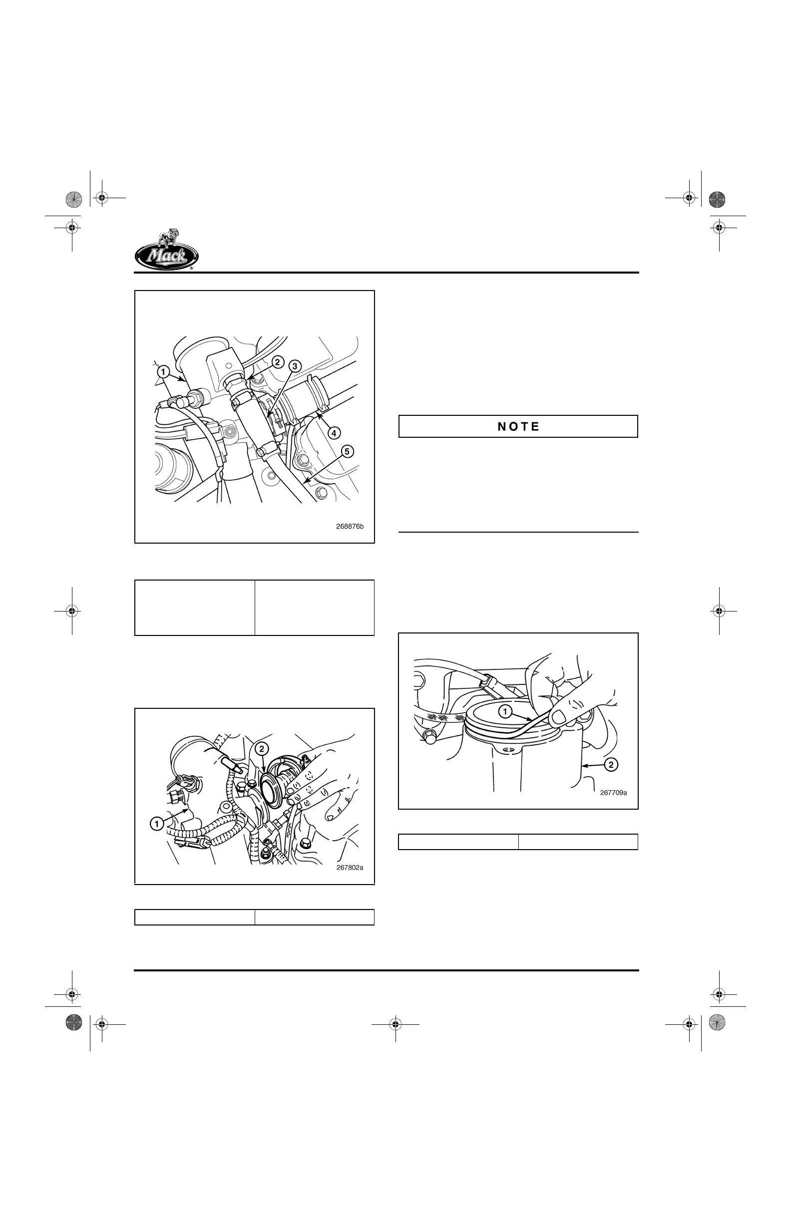
Figure 508 — Boost Pressure Relief Valve (Turbo
By-Pass)
3. Loosen and remove the clamp attaching the
upper EGR gas tube to the EGR gas mixer
tube (Figure 509). Remove and discard the
seal in the gas-tube flange.
509
Figure 509 — EGR Tube-to-Mixer Connection
4. Remove the capscrew from the support
bracket at the side of the EGR gas mixer
tube. The bracket is attached between the
mixer tube and the coolant manifold.
5. Remove the capscrews attaching the mixer
tube to the inlet manifold (Figure 507) and
remove the tube.
INSTALLATION PROCEDURE
EGR gas tube clamps can be reused if there is no
damage and the threads are not corroded.
However, with damaged or corroded threads, the
clamps cannot be tightened to the proper torque
specification for a gas-tight seal. Clamps used on
the hot-side tube are prone to corrosion and
damage and should be replaced.
1. Clean and inspect the mating flange of the
upper EGR gas tube. Install a new graphite
wire-mesh seal in the flange.
2. Clean and inspect the mounting collar on the
inlet manifold. Then, install a new O-ring on
the collar (Figure 510).
510
Figure 510 — O-Ring Installation
1. EGR Gas Mixer Tube
2. Boost Pressure Relief
Valve (Turbo By-Pass)
3. Valve-to-Outlet Tube
Coupling
4. EGR Gas Tube
(Reference)
5. Outlet Tube-to-Exhaust
1. EGR Gas Mixer 2. Upper EGR Gas Tube
1. O-Ring 2. Inlet Manifold
5-111.bk Page 418 Monday, July 10, 2006 2:26 PM