Page 60
DESCRIPTION AND OPERATION
67
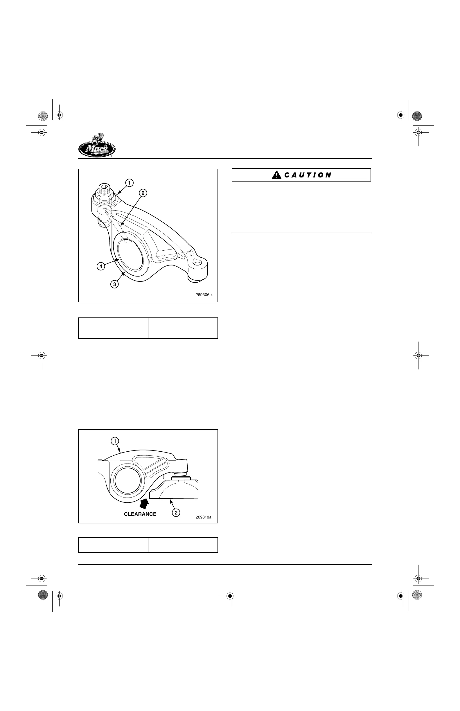
Figure 67 — Rocker Arms
Rocker Arm Adjusting Screws
앫 The pressure oil fed adjusting screws are
Armolloy coated for resistance to galling and
wear
Pinless Valve Yoke
앫 The top inboard corner of yoke has been
chamfered at a 45-degree angle, necessary
to ensure clearance between yoke tip and
the heavier rocker arm casting
68
Figure 68 — Pinless Valve Yoke
The revised rocker arm components described
above cannot be intermixed with previous version
components.
With the heavier rocker arms, it is mandatory to
use the pinless valve yoke having the chamfered
tip at the top of the inboard end.
Low-Pressure Fuel System
ASET™ AC engines have a cooling plate in the
low pressure fuel circuit (Figure 69) to provide
cooling for the higher capacity EECU. Fuel flows
from the fuel tank to the EECU cooling plate, the
pre-pump filter, the supply pump, the primary
filter (combination primary and secondary) and
then to the unit pumps.
In addition to the standard arrangement
described above, Figure 70 illustrates a system
equipped with the optional fuel filtration
arrangement. With this arrangement, the supply
pump is replaced with a traditional pump that
does not have the integral pre-pump screen and
spin-on filter.
To decrease restriction in the low-pressure fuel
system, hoses and fittings with larger inside
diameters are used for all suction lines in the
system.
To meet unit pump demands, the supply pump
provides a 100 gph fuel flow at 70 psi pressure.
This high level of flow and pressure is needed to
cool the unit pumps and EECU, and keep the fuel
supply gallery filled. Pressure within the gallery is
maintained by a pressure regulating valve with a
70 psi spring setting. A check valve fitting located
at the fuel return gallery outlet on the cylinder
block right side prevents the system from
bleeding down when the engine is not operating.
The gear-type supply pump driven by the engine
camshaft gear is located on the rear side of the
right-front flange of the cylinder block. The pump
is also fitted with a hand primer pump for all AC
engine applications. In addition, the standard AC
configuration also includes integral pre-pump and
primary filters.
1. Wider Casting at Nut
Flange
2. Revised Oil Passage
3. Near-Full Width Casting
4. Steel Bushing
1. Heavier Rocker Arm
Casting
2. Yoke with Chamfered Tip
5-111.bk Page 60 Monday, July 10, 2006 2:26 PM