Page 68
DESCRIPTION AND OPERATION
Cylinder Head
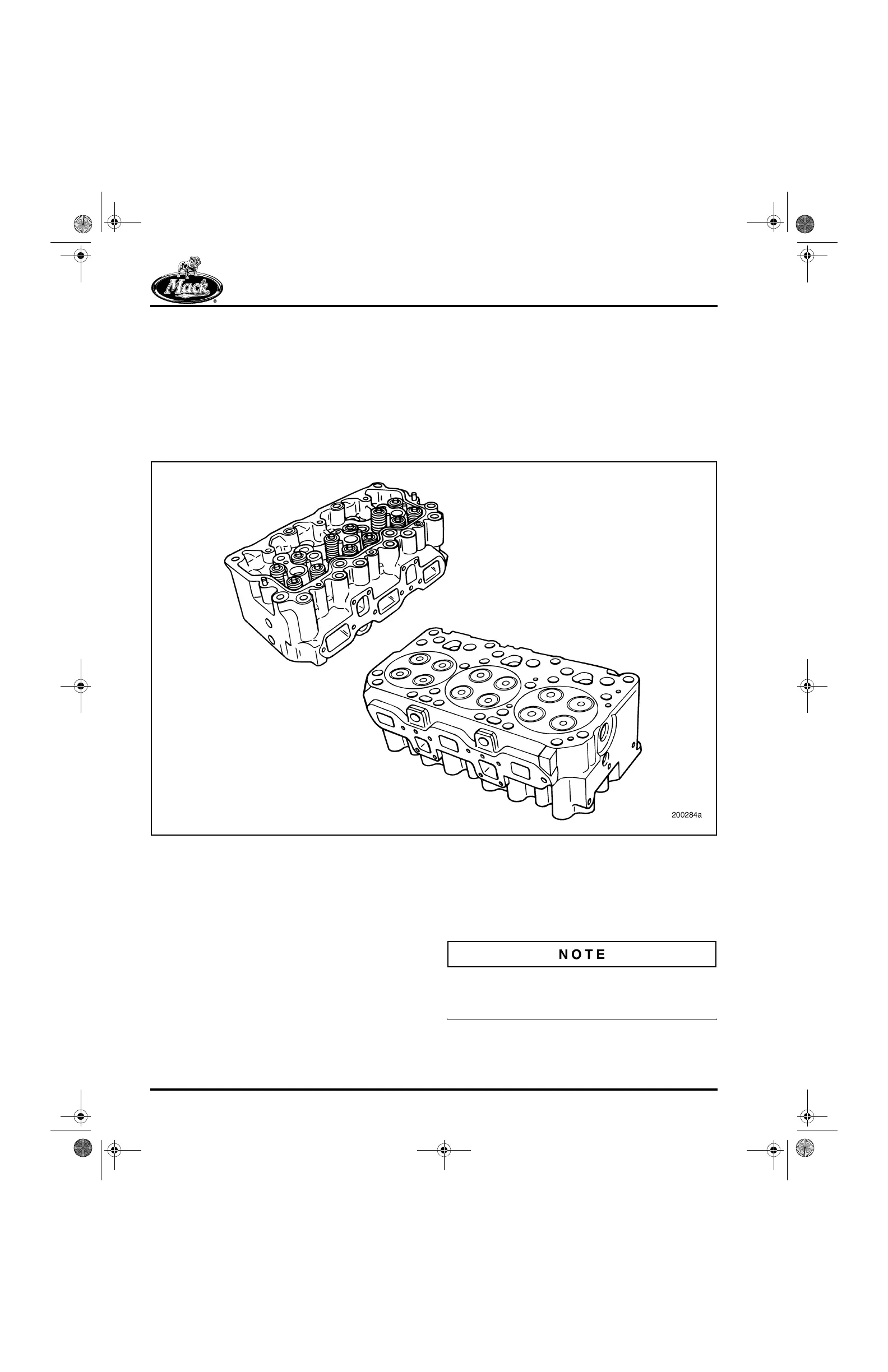
The cast-iron cylinder head (Figure 77) is
constructed using a special iron alloy. The head
contains cored inlet, exhaust and coolant
passages, drilled oil passages, replaceable inlet
and exhaust guides and seats, various drilled
passages and tapped holes. Each cylinder head
covers three cylinders and has two inlet and two
exhaust valves per cylinder. Circular grooves in
the deck surface correspond with the fire ring
bead on the cylinder sleeves. This design sets
the fire ring directly over the liner. With the
cylinder head installed and the bolts tightened to
specification, the liner coining bead extrudes the
fire ring into the cylinder head groove, providing a
positive combustion pressure seal.
77
Figure 77 — Cylinder Head
Some characteristics of the cylinder head are not
visually evident, but are still significant
(Figure 78). They include the following listed
items:
앫 Push rod holes are angled at four degrees
due to outboard location of camshaft.
앫 Large nozzle sleeve diameter to
accommodate 22 mm nozzle holder
assembly with no leak off return.
앫 Water-jacket casting designed to improve
coolant flow.
앫 Lower exhaust stud holes intersect with
push rod holes; upper exhaust holes may
intersect as well. This requires that all
exhaust studs be sealed at installation to
prevent oil weepage.
ASET™ and E7 cylinder heads cannot be
interchanged because of the differences in the
machining.
5-111.bk Page 68 Monday, July 10, 2006 2:26 PM