Page 334
REPAIR INSTRUCTIONS, PART 1
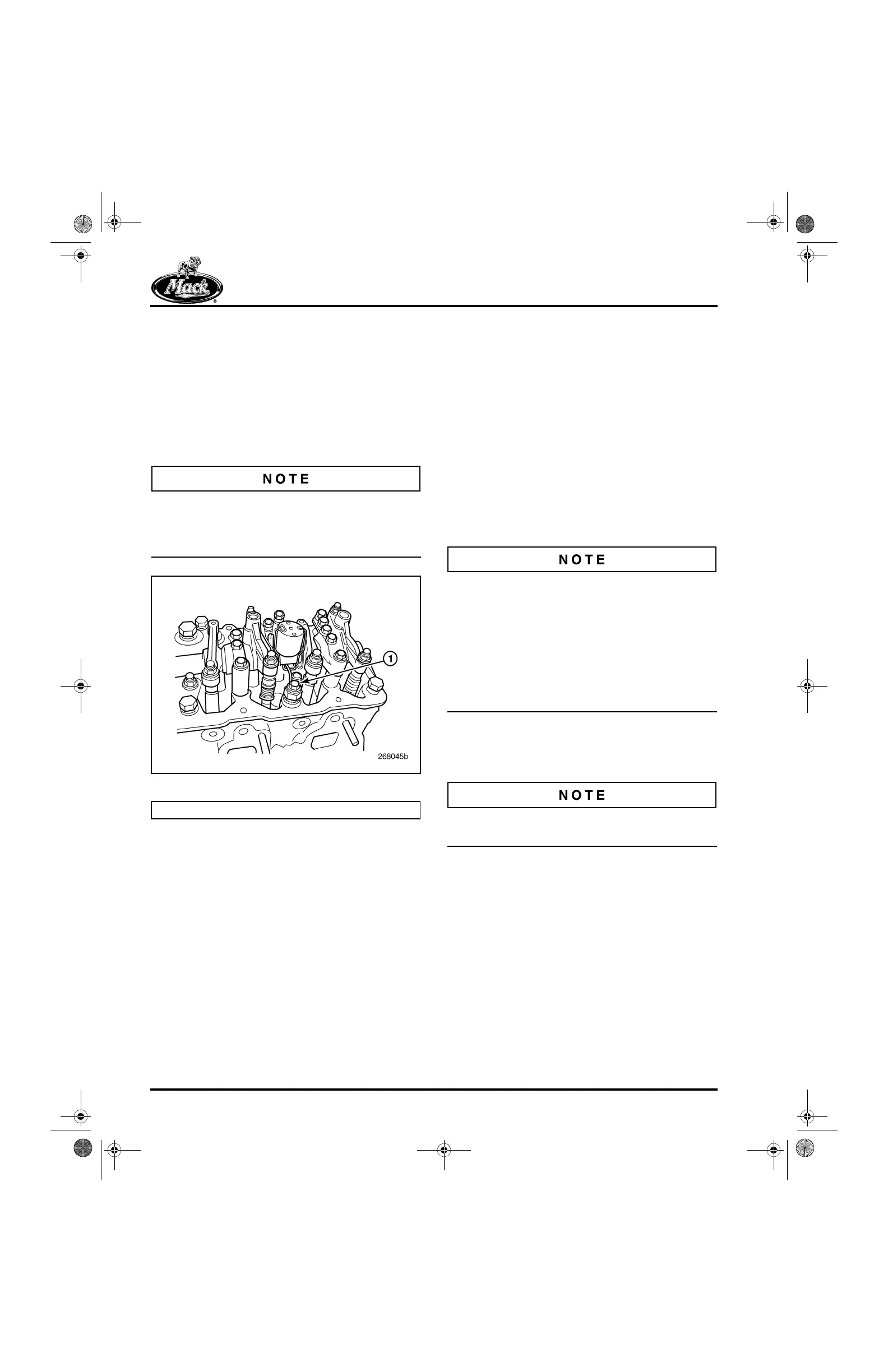
7. After the rocker shaft assembly has been
installed, route the solenoid ground wire
under the rocker shaft and up through the
end of the solenoid retainer clip. Secure the
ground wire terminal to the cylinder head
mounting bolt located directly to the right of
the solenoid. This mounting bolt has a
threaded hole in the center of the bolt head.
Use a bolt and flat washer to secure the
ground wire.
While tightening the ground wire terminal
retaining bolt, do not allow the terminal to rotate
and twist the wire. Use of the flat washer will
prevent this from occurring.
390
Figure 390 — Engine Brake Solenoid Ground Wire
Cylinder Head Cover and Spacer
Installation
[213 JB]
GENERAL INFORMATION
A one-piece gasket is used as a seal for the
cylinder head cover (and spacer, if equipped with
a J-Tech™ engine brake). Sealing compounds
are NOT required for this type of gasket. To
reduce noise, isolating-type mounting hardware
is used to secure the cover to the cylinder head.
To prevent heat-related damage which can occur
to the cylinder head cover/J-Tech™ engine brake
spacer gaskets, particularly in the area of the
turbocharger, a new gasket is now available for
all ASET™ engines. The new gasket, which is
made from Vamac
®
G, a material more resistant
to hot oil, was phased into production
late-December 2002, beginning with serial
No. 2Y0622.
In addition to the cylinder head cover gasket, new
isolators were implemented into production along
with the new gaskets. These isolators are
manufactured of a harder material to provide the
adequate “crush” necessary for the new gasket
material.
앫 When replacing a previous style gasket with
the new-style gasket, the existing isolators
must also be replaced with the new-style
isolators.
앫 The new cylinder head cover/J-Tech™
spacer gaskets and isolators are easily
identifiable by their color. The new gasket
and isolators are black in color, whereas the
previous parts were gray.
INSTALLATION PROCEDURE
Refer to Figure 391.
Installation procedures for the spacer and the
cylinder head cover seal are identical.
1. Install a seal in the seal groove of each
spacer (if so equipped) and cylinder head
cover groove.
a. Thoroughly clean the seal contact
surface on the cylinder head and seal
contact surface on the spacer (if so
equipped).
b. Install the offset joined section of the
seal in the widened section of the seal
groove in the cylinder head cover or
spacer.
c. Guide the seal into the groove around
the circumference of the cylinder head
cover or spacer.
1. Ground Wire Location
5-111.bk Page 334 Monday, July 10, 2006 2:26 PM