Page 380
REPAIR INSTRUCTIONS, PART 2
4. Secure the lifter in the UP position with
grommets provided with the tappet holders.
The holding tool shafts of two adjacent valve
lifters can be prevented from dropping by
wrapping a rubber band around the two
shafts. This draws the shafts together and
holds them in position. Refer to Figure 450.
5. Repeat steps 2 through 4 to install each of
the remaining valve lifters.
6. Apply a generous coating of clean engine oil
to the camshaft bushings.
7. Clean the camshaft with a suitable solvent.
8. Apply clean engine oil completely around
the running surfaces of the camshaft lobes
and bearing journals. Lubriplate-type grease
may be substituted for engine oil.
Make sure the captured thrust washer and
camshaft gear are properly installed on the
camshaft.
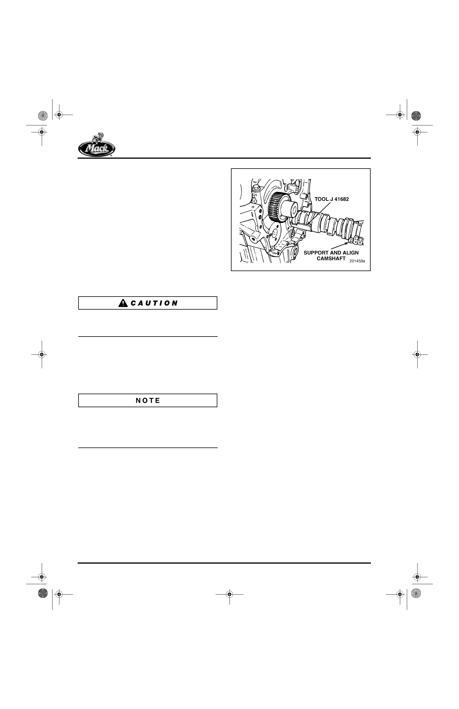
9. Install the camshaft installation guide tool
over the large flat of the injector lobe,
between the last two cam journals (journals
at back of shaft).
10. Apply clean engine oil to the installation
guide.
The camshaft is heavy, approximately 90 pounds
with the gear. The installation guide allows the
camshaft to slide from one cam bushing to the
next without allowing the cam to drop when one
journal clears the bushing bore.
11. Slide the camshaft into the block with the
cam installation guide facing down toward
the floor. Refer to Figure 454.
12. Slide the cam all the way into the block.
454
Figure 454 — Camshaft Installation
13. After the camshaft is fully installed, install
the thrust washer screws and tighten to
specification.
14. Rotate the crankshaft and camshaft to
facilitate installation guide removal. The
camshaft must be rotated so that the
installation guide faces the cylinder block
pan rail. The crankshaft must be rotated so
the No. 6 connecting rod journal faces the
cylinder block top deck (piston at TDC).
15. Remove the installation guide tool J 41682.
Camshaft Idler Gear Installation
[213]
Before installing the idler gear/hub assembly,
determine which is the top mounting hole on the
hub.
The idler gear is held in place by a flanged hub
mounted to the cylinder block by three bolts.
Although the bolt-mounting pattern may appear
symmetrical, it is not. The non-symmetrical
mounting pattern ensures that the oil feed
passages in the hub will be properly aligned with
the oil feed passage in the cylinder block, which
lubricates the idler gear hub bushing.
To aid in aligning the hub to the mounting holes in
the cylinder block, the hub mounting-bolt hole at
the 12 o’clock position (engine upright) is
identified by the word “UP” steel-stamped just
below the mounting hole. Refer to Figure 455.
5-111.bk Page 380 Monday, July 10, 2006 2:26 PM