Page 360
REPAIR INSTRUCTIONS, PART 1
EECU and Cooling Plate Installation
[230 EA]
The EECU cooling plate mounting arrangement
was changed in mid-May 2003 to eliminate a
tolerance stack-up condition that may leave each
isolator loose even though the nut securing them
is torqued properly. To correct this condition
reinstall the cooling plate using the following
procedure:
Non-Current Cooling Plate Design
The EECU cooling plate used on ASET™ AC
engines from the beginning of production through
mid-May 2003 has two 0.580-inch (14.7 mm)
diameter mounting holes at the lower corners of
the plate. The lower mounting isolators are
installed through these holes, and each isolator is
then secured with two 0.188-inch thick washers
and one nut.
Due to tolerance stack-up between the thickness
of the cooling plate and the dimensions of the
isolators, some isolators may not clamp onto the
cooling plate when the nut is tightened. When this
occurs, tightening the nut further will cause the
washers to rotate, which places force on the
rubber portion of the isolator, resulting in tearing
or breaking of the rubber. To prevent this from
occurring, it is recommended that another washer
(part No. 35A1446X) be added between the two
0.188-inch washers. This should be done
whenever the EECU or cooling plate is removed
for any reason, or if torn or broken mounting
isolators are encountered.
1. For the non-current cooling plate design,
upper isolators are secured with flanged
nuts only; washers are not used. The upper
mounting nuts must be tightened to 108 lb-in
(12 N폷m).
2. Non-current lower mounting nuts must be
tightened to 180 lb-in (20 N폷m).
Current Cooling Plate Design
Beginning 5/15/03, the EECU cooling plate
arrangement used on the ASET™ AC
engines was changed to include integral
bushings at the two lower mounting bolt
holes. The lower mounting isolators are
installed through these bushings and
secured by one 0.065-inch thick washer and
one nut.
3. For the current cooling plate design, upper
isolators are secured with flanged nuts only;
washers are not used. The upper mounting
nuts must be tightened to 108 lb-in (12 N폷m).
4. Current design lower mounting nuts must be
tightened to 180 lb-in (20 N폷m).
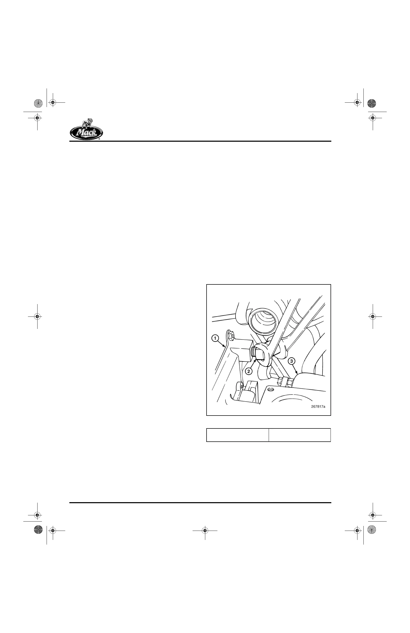
5. Connect the fuel lines to the inlet and outlet
ports of the cooling plate (Figure 434).
434
Figure 434 — Cooling Plate Fuel Lines
1. Cooling Plate
2. Fuel Line
3. Thermostat Housing
5-111.bk Page 360 Monday, July 10, 2006 2:26 PM